Piezoelectric Sensors in Biomedical and Biological Applications
Technical News

Piezoelectric transducers and dynamic mechanical sensors play an expanding role across diagnostic, therapeutic, and continuous health-monitoring medicine. Applications span non-invasive cardiovascular pulse-wave profiling, respiratory rhythm tracking, implantable cardiac energy harvesting, micro-machined ultrasonic imaging catheters (IVUS), acoustic drug delivery, and orthopedic osseointegration monitoring. Because piezoelectric materials operate via the direct electromechanical effect—generating dielectric surface polarization charges in direct response to applied mechanical stress without requiring external bias power—they enable ultra-low-power, self-powered wearable and bio-implantable sensing nodes.
However, transitioning piezoelectric materials from industrial robotics to the human body introduces severe metrological and material design boundaries:
- Biological Soft-Tissue Acoustic Matching: Human tissue possesses a characteristic acoustic impedance of approximately 1.5 MRayls. Rigid inorganic piezoceramics exhibit severe acoustic reflection unless matched.
- Sub-Hertz Physiological Frequency Constraints: Vital signs (such as resting heart rates of 1 Hz or respiration cycles of 0.2 Hz) generate ultra-low-frequency mechanical inputs where charge leakage causes signal decay.
- Biocompatibility and Cytotoxicity: The clinical phase-out of lead-containing materials (governed by ISO 10993-1) drives intense research into lead-free perovskites, biocompatible fluoropolymers, and bio-resorbable biopolymers such as poly(L-lactic acid) (PLLA).
Designing and validating medical-grade piezoelectric sensors requires navigating constitutive electromechanical equations, charge amplifier transfer functions, acoustic impedance matching, and dynamic micro-force testing protocols in compliance with IEEE Std 176 and IEC 60601-1.
Electromechanical Sensor Physics: Charge Mode versus Voltage Mode
When an alternating physiological stress T3(t) = F_dynamic(t) / A is exerted on a piezoelectric sensor element of thickness h, cross-sectional area A, and relative permittivity epsilon_r, the generated electrical response is evaluated in two operational modes:
+---------------------------------------------------------------------------------------------------+
|                        Piezoelectric Sensor Transduction Boundaries                               |
+---------------------------------------------------------------------------------------------------+
|                                                                                                   |
|           Direct Physiological Force Input F(t) (Pulse Wave / Respiration / Acoustic)             |
|                                       |                                                           |
|                                       v                                                           |
|  [Charge Mode Sensing: Short-Circuit]                [Voltage Mode Sensing: Open-Circuit]         |
|  Q(t) = d33 * F(t)                                   V_out(t) = g33 * (F(t) / A) * h              |
|  Virtual-Ground Charge Amplifier                     High-Impedance Electrometer Buffer           |
|  - Completely immune to cable capacitance            - Attenuated by cable stray capacitance      |
|  - Bandwidth: f_lower = 1 / (2*pi*R_f*C_f)           - Bandwidth: f_lower = 1 / (2*pi*R_in*C_tot) |
+---------------------------------------------------------------------------------------------------+
1. Charge-Mode Sensing Architecture
In charge mode, the sensor electrodes are connected to a virtual-ground charge amplifier (transimpedance topology). The short-circuit charge (Q) generated across the electrodes is proportional only to the longitudinal piezoelectric charge coefficient (d33) and applied force:
Q(t) = d33 * F_dynamic(t)
The generated charge is transferred onto an external feedback capacitor (C_feedback) shunted by a feedback resistor (R_feedback). The output voltage V_out(omega) is described by the frequency-dependent transfer function:
V_out(omega) = - [ Q(omega) / C_feedback ] * [ (j * omega * R_feedback * C_feedback) / (1 + j * omega * R_feedback * C_feedback) ]
The lower cut-off frequency (-3 dB corner) is governed exclusively by the feedback network:
f_lower = 1 / (2 * pi * R_feedback * C_feedback)
The Primary Advantage for Biomedical Monitoring: Because the sensor terminals are held at virtual ground (0 V), zero charge accumulates across the input cable capacitance (C_cable). The calibration factor (volts per Newton) remains completely invariant regardless of patient movement, cable length, or lead wire flexing.
2. Voltage-Mode Sensing Architecture
In voltage mode, the sensor connects to an electrometer buffer with high input resistance (R_in > 1e12 ohms). The generated open-circuit voltage is dictated by the piezoelectric voltage coefficient g33:
V_out(t) = g33 * (F(t) / A) * h = [ d33 / (epsilon_0 * epsilon_r) ] * [ F(t) / A] * h
While voltage sensitivity scales inversely with relative permittivity (making low-permittivity polymers like PVDF highly responsive), it is vulnerable to parasitic attenuation:
V_measured = V_out * [ C_sensor / (C_sensor + C_cable + C_in) ]
For small wearable epidermal patches where C_sensor is only 50 pF, a 1-meter coaxial cable (100 pF) drops the measured physiological signal by 67%. Charge-mode amplification is therefore standard in clinical instrumentation.
Acoustic Impedance Matching for Medical Ultrasound
For medical diagnostic imaging (B-mode ultrasound, Doppler blood-flow velocimetry) and therapeutic focused ultrasound (HIFU), the transducer must efficiently transmit and receive acoustic waves into biological soft tissue.
Acoustic Boundary Reflection:
Acoustic Wave ---> [Piezoelectric Active Layer (Z_1)] ===> [Biological Tissue (Z_2)]
                         \
                          \---> Reflected Acoustic Wave: R_acoustic = (Z_2 - Z_1)^2 / (Z_2 + Z_1)^2
The specific acoustic impedance (Z_acoustic, in units of Rayls or kg/(m2 * s)) is the product of material mass density (rho) and longitudinal sound velocity (v_sound):
Z_acoustic = rho * v_sound
At an interface between two media with acoustic impedances Z_1 and Z_2, the acoustic power reflection coefficient (R_power) under normal incidence is:
R_power = [ (Z_2 - Z_1) / (Z_2 + Z_1) ]^2
The table below contrasts the acoustic matching parameters of leading biomedical piezoelectric materials against human soft tissue.
| Material Classification | Material Density rho (g/cm3) | Sound Velocity v_long (m/s) | Acoustic Impedance Z (MRayls) | Acoustic Reflection at Tissue Interface (R_power) | Matching Layer Requirement |
|---|---|---|---|---|---|
| Human Soft Tissue | ~1.05 | 1,540 | 1.54 | 0.0% (Ideal Baseline) | None (Target Medium) |
| PZT-5H Ceramic | 7.50 to 7.80 | 4,000 to 4,300 | 30.0 to 33.5 | 82.0% to 84.5% (Severe Reflection) | Mandatory 1 to 2 quarter-wave (lambda/4) matching layers |
| 1-3 Piezocomposite (PZT/Polymer) | 3.80 to 4.50 | 3,200 to 3,600 | 12.0 to 16.0 | 59.0% to 68.0% (Moderate) | Single matching layer required |
| Barium Titanate (BaTiO3) | 5.80 to 6.00 | 4,400 to 4,600 | 25.5 to 27.6 | 78.0% to 80.0% | Mandatory impedance matching stack |
| PVDF Fluoropolymer | 1.76 to 1.80 | 2,200 to 2,400 | 3.9 to 4.3 | 19.0% to 22.0% (Excellent Match) | Direct tissue contact without matching layer |
| P(VDF-TrFE) Copolymer | 1.85 to 1.90 | 2,300 to 2,500 | 4.2 to 4.7 | 21.0% to 25.0% (Excellent Match) | Direct skin contact for wearable patches |
For high-impedance PZT ceramics (Z_piezo approx 33 MRayls), over 83% of the emitted acoustic power reflects immediately off the skin barrier. To bridge this mismatch, an intermediate quarter-wave (lambda/4) matching layer must be deposited on the transducer face. The ideal acoustic impedance (Z_matching) of the matching layer is:
Z_matching = sqrt(Z_piezo * Z_tissue) = sqrt(33 * 1.54) approx 7.1 MRayls
Acoustic matching layers are fabricated by compounding heavy metal oxides (e.g., Al2O3, CeO2, or tungsten sub-micron powders) into low-viscosity epoxy resins to tune Z_matching precisely to 7 MRayls. Conversely, piezoelectric fluoropolymers (PVDF and P(VDF-TrFE)) possess intrinsic acoustic impedances between 3.9 and 4.7 MRayls, closely matching water and soft tissue without matching layers.
Biomedical Material Benchmark: Lead-Free, Flexible, and Bio-Resorbable Transducers
The table below compiles physical, electromechanical, and biological safety figures of merit for the six major piezoelectric material families evaluated in biomedical devices.
| Material System | Chemical Composition | Piezoelectric Charge d33 (pC/N) | Voltage Factor g33 (1e-3 V*m/N) | Hydrostatic Figure of Merit (d_h * g_h) | Biocompatibility (ISO 10993) | Primary Clinical Application |
|---|---|---|---|---|---|---|
| PZT-5A / PZT-5H | Pb(Zr_x Ti_1-x)O3 | 400 to 650 | 20 to 30 | 50 to 120 (1e-15 m2/N) | Cytotoxic (Lead leaching risk); requires hermetic encapsulation | External ultrasound probes, therapeutic HIFU |
| Barium Titanate (BaTiO3) | BaTiO3 (Perovskite) | 150 to 250 | 14 to 20 | 80 to 150 | Non-toxic; lead-free bone tissue engineering scaffolds | Osteogenic bone regeneration stimulation |
| KNN Lead-Free Ceramic | (K,Na)NbO3 - Li/Ta modified | 200 to 420 | 25 to 35 | 120 to 280 | Biocompatible (biocompatibility proven in vivo) | Lead-free surgical scalpels, implantable sensors |
| PVDF Flexible Film | -(C2H2F2)_n- (Beta-phase) | -25 to -35 | 180 to 240 | 1,500 to 3,500 (Exceptional) | Fully biocompatible, non-resorbable, skin-conformable | Epidermal pulse sensors, respiratory monitors |
| P(VDF-TrFE) Copolymer | P(VDF-TrFE) 75/25 mol% | -30 to -42 | 220 to 300 | 2,200 to 4,800 | Biocompatible, spin-coatable onto flexible MEMS | Flexible skin-wearable arrays, catheter sensors |
| PLLA Biopolymer | Poly(L-lactic acid) | 10 to 15 (shear d14) | 150 to 200 | N/A (Shear dominant) | 100% Bio-resorbable; degrades safely to lactic acid | Fully biodegradable transient implant monitors |
Sub-Hertz Physiological Charge Metrology: Pitfalls and Solutions
Evaluating wearable and implantable piezoelectric sensors requires capturing ultra-low-frequency mechanical motions. The table below compiles the primary measurement challenges encountered during sub-hertz testing and their corresponding engineering solutions.
| Experimental Challenge | Physical Root Cause | Observed Signal Artifact | Low-Noise Engineering Countermeasure |
|---|---|---|---|
| Triboelectric Contact Noise | Micro-sliding between test fixture tips and flexible sensor metallization | Spurious charge spikes (>100 pC) swamping heartbeat waveforms | Implement spherical sapphire tips with conductive silicone elastomeric pads |
| Sub-Hertz Signal Decay | Finite insulation resistance (R_sensor | R_amp) drains charge before peak | |
| Pyroelectric Interference | Body heat fluctuations (dT/dt) generate large pyroelectric displacement currents | Drifting DC voltage baseline; false pulse wave amplitude | Employ differential twin-sensor configurations with inverted poling axes |
| Motion Flexure Coupling | Patient movement bends sensor substrate, exciting transverse d31 modes | High-amplitude motion artifacts obscuring subtle pulse signals | Restrict active area to neutral mechanical flexural plane of substrate |
| Mains 50/60 Hz Induction | High-impedance wiring picks up ambient electromagnetic radiation | Large sinusoidal hum masking micro-volt bio-signals | Implement active driven-right-leg (DRL) shielding and lock-in filtering |
The Differential Pyroelectric Cancellation Architecture
Because all polar ferroelectric materials are inherently pyroelectric (generating current I_pyro = p * A * (dT/dt)), attaching a sensor to human skin introduces thermal drift: localized blood perfusion or ambient air drafts generate false voltage baselines.
+---------------------------------------------------------------------------------------------------+
|                        Differential Pyroelectric Cancellation Architecture                        |
+---------------------------------------------------------------------------------------------------+
|                                                                                                   |
|  Mechanical Force F(t)              Mechanical Force F(t)                                         |
|         |                                  |                                                      |
|         v                                  v                                                      |
|  +--------------+                   +--------------+                                              |
|  | Element 1    | Poling Up (+P)    | Element 2    | Poling Down (-P)                             |
|  | Piezo + Pyro |                   | Piezo + Pyro |                                              |
|  +--------------+                   +--------------+                                              |
|         |                                  |                                                      |
|         | I_1 = +I_piezo + I_pyro          | I_2 = -I_piezo + I_pyro                              |
|         \----------------+-----------------/                                                      |
|                          |                                                                        |
|                          v                                                                        |
|               [Differential Amplifier] ===> Net Output: I_out = I_1 - I_2 = 2 * I_piezo           |
|                                             (Thermal Pyroelectric Current I_pyro Cancelled!)      |
+---------------------------------------------------------------------------------------------------+
By connecting two identical sensor elements in anti-parallel polarization, the common-mode thermal current (I_pyro) cancels out, while the mechanical signal doubles, ensuring pristine physiological pulse waveforms.
Dynamic Force and Micro-Load Metrology Platforms
Accurately qualifying wearable films and biomedical sensors requires mechanical loading platforms capable of applying calibrated, millinewton-level dynamic forces while maintaining rigid contact stability. Standard industrial Berlincourt meters apply fixed, heavy static loads (often 2 N to 5 N) through unyielding clamps, crushing ultra-thin biocompatible polymers or flexible silicon membranes.
The MatMeas PEAI-1000 High-Precision Piezoelectric Analyzer provides independent closed-loop servo control of static clamping preload (1.0 N to 10.0 N) and dynamic sinusoidal force (0.05 N to 0.5 N). Featuring built-in lock-in amplification, it separates minute physiological-scale displacement charges from ambient electromagnetic interference, delivering high-fidelity d33 and g33 sensitivity measurements across an ultra-wide dynamic range (0 to 2000 pC/N) with +/-2% accuracy.
For sensor durability evaluations requiring continuous force-frequency profiling across variable operational regimes (e.g., simulating walking impacts, respiratory cycles, or acoustic vibration from 30 Hz to 300 Hz), the MatMeas PEMS-1000 In-Situ Dynamic Piezoelectric System provides an integrated electrodynamic shaker with real-time load cell monitoring. Its dynamic force control prevents baseline drift, enabling accelerated fatigue and linearity testing of packaged wearable transducers across millions of loading cycles.
Best-Practice Laboratory SOP for Biomedical Piezoelectric Sensor Testing
To produce audit-compliant, clinically relevant characterization data:
- Sensor Packaging and Electrode Inspection:
- Encapsulate flexible sensors in medically graded, pinhole-free polydimethylsiloxane (PDMS) or parylene-C (thickness 5 um to 10 um) to block ionic moisture ingress.
- Confirm that top and bottom flexible electrodes (e.g., serpentine gold or silver nanowire networks) maintain electrical continuity under 20% tensile strain.
- Mounting on Physiological Tissue Phantoms:
- Mount the sensor onto a certified ballistic gelatin or silicone tissue phantom (Shore 00-30 hardness) with calibrated elastic modulus (Young's modulus E = 50 to 150 kPa) to simulate human skin compliance.
- Electrometer and Charge Amplifier Calibration:
- Configure a low-noise charge amplifier with feedback capacitor C_f = 1.0 nF and feedback resistor R_f = 100 gigaohms, establishing a lower cut-off frequency f_lower = 0.0016 Hz (ensuring unattenuated response down to 0.05 Hz).
- Verify that electrometer input bias current remains below 10 femtoamperes.
- Controlled Cyclic Force Application:
- Align the mechanical exciter tip over the active sensing area of the transducer.
- Apply a static physiological pre-compression force F_static = 0.50 N (+/-0.02 N), simulating the gentle pressure of an adhesive medical patch or medical wristband.
- Superimpose an alternating sinusoidal force delta_F = 0.10 N at frequencies representative of physiological signals (0.5 Hz for respiration, 1.2 Hz for resting pulse, 20 Hz for heart sounds).
- Linearity and Dynamic Range Profiling:
- Step the dynamic force amplitude from 0.01 N up to 2.0 N across 15 logarithmic steps.
- Record generated charge (Q_rms) and compute charge sensitivity: S_Q = Delta Q / Delta F (in pC/N).
- Confirm that correlation coefficient R^2 exceeds 0.999 across the physiological pressure band (0.1 kPa to 20 kPa).
- Accelerated In-Vitro Saline Endurance Cycling:
- Immerse the encapsulated sensor in Phosphate-Buffered Saline (PBS, pH 7.4) maintained at physiological body temperature (37.0 C +/- 0.5 C).
- Subject the device to 1e6 continuous cycles of cyclic mechanical loading at 5 Hz.
- Continuously monitor insulation resistance and piezoelectric charge sensitivity. Any drop in insulation resistance below 1 gigaohm indicates hermetic seal failure.
Frequently Asked Questions (FAQ)
Why can't a piezoelectric sensor measure truly static physiological pressures indefinitely?
Piezoelectric materials operate strictly via transient dielectric polarization. When a static, constant mechanical force is applied, a fixed surface charge (Q = d33 * F_static) appears across the electrodes. However, in any physical system, this charge immediately begins to drain through the material's internal volume resistance (R_volume) and the input resistance of the external amplifier (R_in). The voltage decays exponentially with a time constant tau = R_parallel * C_total. After a time interval t > 5 * tau, all generated charge is exhausted, and the measured voltage drops to zero even though the static force is still applied. True static pressure monitoring requires piezoresistive or capacitive sensors, while piezoelectric sensors excel at capturing dynamic, pulsating physiological waveforms.
What makes PLLA an attractive candidate for transient, bio-resorbable medical implants?
Poly(L-lactic acid) (PLLA) is an FDA-approved bio-resorbable aliphatic polyester that degrades in vivo via non-enzymatic hydrolytic chain scission into lactic acid, a natural metabolic intermediate excreted as carbon dioxide and water. When PLLA polymer chains are drawn and uniaxially oriented, the material exhibits significant shear piezoelectricity (d14 approx 10 to 15 pC/N) arising from the non-centrosymmetric alignment of polar carbonyl (C=O) groups. PLLA requires zero electrical poling treatment (it is not ferroelectric), exhibits zero cytotoxic heavy-metal leaching, and naturally dissolves after fulfilling its temporary physiological sensing or bone-growth stimulation mission, eliminating the need for surgical removal.
How does acoustic impedance mismatch degrade medical ultrasound imaging resolution?
When an ultrasound transducer emits acoustic waves into biological tissue, an acoustic impedance mismatch between the piezoceramic core (Z approx 33 MRayls) and tissue (Z approx 1.5 MRayls) causes severe energy reflection at the front face (R_power > 80%). This reflection severely attenuates the acoustic power entering the patient's body. Furthermore, acoustic waves reflecting internally between the transducer electrodes create "ringing" reverberation tails, lengthening the emitted acoustic pulse in time. In pulse-echo ultrasound, axial spatial resolution is governed by the spatial pulse length (SPL = N_cycles * lambda / 2). Excessive ringing ruins axial image resolution. Applying tailored acoustic matching layers dampens internal ringing, maximizes energy transfer, and sharpens imaging resolution.
Related Instruments & Equipment
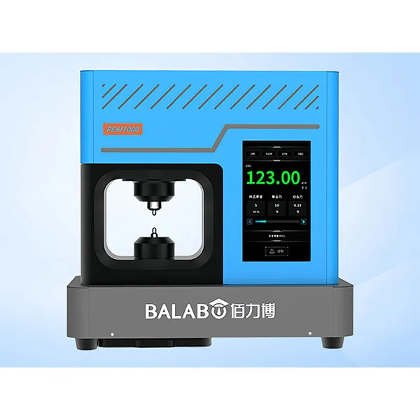
MatMeas PEAI1000 High-Precision Piezoelectric Analyzer
The MatMeas PEAI1000 is a next-generation High-Precision Piezoelectric Analyzer engineered to evaluate the piezoelectric coefficient (d33) of advanced functional materials. Surpassing the limitations of traditional d33 measuring instruments, it employs an advanced dynamic measurement method integrated with cutting-edge lock-in amplification technology. This architecture strictly suppresses environmental noise, significantly improving the signal-to-noise ratio. Capable of applying variable static clamping forces (1~10N) and precise dynamic test forces (0.1~0.5N), it guarantees an ultra-wide measurement range (0 to 2000 pC/N) with an exceptional accuracy of ±2%. It is an essential, highly reliable tool for the research, application, and mass production of piezoelectric blocks, plates, and delicate thin films.
View details →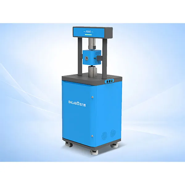
MatMeas High Precision In‑situ d33 Piezoelectric Measurement System – PEMS Analyzer
MatMeas PEMS is a high‑precision in‑situ d33 piezoelectric measurement system for advanced material characterization.
View details →Request High-Precision Testing Solutions
Get expert guidance and customized instruments for your functional materials project.