5 Core Ferroelectric Testing Techniques for Advanced Materials
Technical News

Ferroelectric materials possess spontaneous electrical polarization that can be repeatedly reversed between stable orientation states through the application of an external electric field. This non-volatile bistability forms the foundational operating principle of next-generation ferroelectric random-access memories (FeRAM), ferroelectric field-effect transistors (FeFETs), electro-optic modulators, and ultra-high-density capacitive energy storage systems. Over recent years, the discovery of robust ferroelectricity in CMOS-compatible, sub-10-nanometer doped hafnium oxide (HfO2-ZrO2 or HZO) thin films has reignited a global race toward ferroelectric semiconductor scaling.
However, translating synthesized ferroelectric thin films, single crystals, or electroceramics into commercially viable electronic devices demands exhaustive metrology. Standard dielectric capacitance measurements fail to capture non-linear domain dynamics, while parasitic leakage currents in sub-micron films frequently distort electrical data, making defective, conductive dielectrics appear deceptively ferroelectric. To establish true material efficacy, characterization laboratories deploy a comprehensive suite of five core ferroelectric testing techniques conforming to IEEE Std 180 and ASTM F668 protocols.
1. Dynamic Polarization-Electric Field (P-E) Hysteresis Loops
The Polarization-Electric Field (P-E) hysteresis loop serves as the definitive diagnostic signature of ferroelectric behavior. By applying a continuous bipolar alternating electric field (typically sinusoidal or triangular waveforms from 10 Hz to 10 kHz), the test forces internal domains through complete polarization reversal cycles.
In modern virtual-ground electrometers, the excitation voltage V(t) is applied across the specimen while the resulting displacement current i(t) is integrated:
P(t) = ( 1 / A ) * ∫ i(t) dt
where A is the electroded active area. A standardized P-E hysteresis loop yields three fundamental material parameters:
- Saturation Polarization (Ps): The maximum polarization achieved under peak applied electric field, where all switchable ferroelectric dipoles align parallel to the external field.
- Remanent Polarization (Pr): The residual dipole polarization retained when the external electric field is ramped back to zero. In FeRAM devices,
2 * Prdefines the operational memory window (distinguishing logic '1' from logic '0'). - Coercive Field (Ec): The reverse electric field required to force the net macroscopic polarization back to zero, defining the voltage threshold needed to write or overwrite a memory cell.
Phenomenologically, the double-well potential governing ferroelectric switching is described by Landau-Ginzburg-Devonshire (LGD) free energy theory:
G = G_0 + (1/2) * α * P^2 + (1/4) * β * P^4 + (1/6) * γ * P^6 - E * P
where α = α_0 * (T - T_0) is the temperature-dependent dielectric stiffness coefficient, β and γ are higher-order expansion parameters, and E is the applied electric field. In classical Sawyer-Tower test circuits, phase lag between sense capacitors and lossy samples causes the hysteresis loop to open artificially into a rounded "cigar" or "banana" shape. High-precision virtual ground systems eliminate this error by maintaining the sensing node at zero virtual potential, preventing voltage-divider phase shifts.
2. Positive-Up-Negative-Down (PUND) Pulsed Transient Testing
In ultra-thin films (such as 10 nm HZO or defective perovskite thin films), standard P-E hysteresis loops are frequently corrupted by high leakage currents and linear dielectric displacement. Severe DC leakage adds a conductive current i_leak = V / R to the displacement current, artificially inflating the apparent remanent polarization.
The Positive-Up-Negative-Down (PUND) pulsed testing protocol completely resolves this ambiguity by decoupling ferroelectric domain switching from linear dielectric charging and conductive leakage through a precisely timed train of five discrete voltage pulses:
Voltage Excitation Pulse Train (PUND)
   +V ┌───┐       ┌───┐
      │ P │       │ U │
      │   │       │   │
  0 V─┴───┴───────┴───┴───────────────────────
                      │   │       │   │
                      │ N │       │ D │
   -V                 └───┘       └───┘
Time ──>  (Preset)   (P)     (U)     (N)     (D)
- Preset Pulse (Negative): Sets all ferroelectric domains into a uniform negative downward polarization state.
- Pulse P (Positive Switching): Applies a positive pulse. The integrated charge
Q_Pcaptures the sum of switchable ferroelectric polarizationQ_sw, linear dielectric displacementQ_linear, and leakage chargeQ_leak:Q_P = 2 * P_r * A + Q_linear + Q_leak - Pulse U (Positive Up, Non-Switching): Applies an identical second positive pulse. Because all switchable domains were already aligned positive by Pulse P, no ferroelectric switching occurs. The charge
Q_Ucaptures strictly:Q_U = Q_linear + Q_leak - Pulse N (Negative Switching): Reverses the electric field to negative polarity, switching domains downward and measuring
Q_N. - Pulse D (Negative Down, Non-Switching): Applies a second negative pulse, measuring non-switching background
Q_D.
The pure intrinsic switchable polarization P_sw is extracted through direct subtraction:
P_sw = ( Q_P - Q_U ) / A = 2 * P_r
By subtracting the non-switching response Q_U from the switching response Q_P, linear capacitance and background leakage are mathematically canceled, proving definitively whether a nanoscale film possesses genuine switchable ferroelectricity.
3. Capacitance-Voltage (C-V) Butterfly Curves and Non-Linearity
While large-signal P-E loops drive full domain reversal, small-signal Capacitance-Voltage (C-V) spectroscopy interrogates reversible domain wall oscillations and dielectric non-linearity. A small AC modulation voltage (typically 50 mV to 100 mV at 100 kHz) is superimposed onto a slowly sweeping DC bias field.
As the DC bias field sweeps from negative to positive saturation, the small-signal capacitance traces a characteristic "butterfly" loop:
- Near the coercive fields
+Ecand-Ec, the capacitance reaches sharp maxima because the material is undergoing active domain wall switching, maximizing polarizability. - At high DC bias fields (
|E| >> Ec), capacitance drops to a low baseline as domains lock in parallel, suppressing domain wall motion.
Plotting C-V curves reveals critical device parameters: flat-band voltage shifts (indicating fixed interfacial trap charges in metal-insulator-semiconductor structures), coercive field symmetry (indicating internal built-in bias fields), and relative dielectric permittivity tunability.
4. Polarization Fatigue and Endurance Degradation
In non-volatile memory applications, ferroelectric capacitors must withstand over 10^10 to 10^15 continuous read/write cycles without performance degradation. Polarization fatigue is the progressive loss of switchable remanent polarization under cyclic bipolar electrical stress.
Fatigue is evaluated by subjecting the specimen to continuous high-frequency bipolar square or triangular pulses (typically 100 kHz to 10 MHz) and periodically executing PUND readouts to track the evolution of 2Pr across elapsed cycle decades.
The physical origin of polarization fatigue is dominated by point defect electromigration:
- Oxygen Vacancy Pinning: Under alternating fields, mobile oxygen vacancies (V_O^••) migrate toward metallic electrode interfaces or grain boundaries, forming trapped charged defect clusters.
- Domain Wall Pinning: These defect agglomerates create intense localized internal electric fields that pin ferroelectric domain walls, preventing them from rotating under external drive.
- Interfacial Dead-Layer Growth: Phase decomposition at the electrode interface creates a non-ferroelectric passive layer that absorbs a fraction of the applied voltage, lowering the effective field delivered to the ferroelectric bulk.
Utilizing conductive oxide electrodes (such as RuO2, IrO2, or SrRuO3) rather than pure platinum (Pt) acts as an oxygen sink, dramatically mitigating vacancy accumulation and extending fatigue endurance beyond 10^12 cycles.
5. Temperature-Dependent Phase Transitions and Energy Storage Metrology
Ferroelectric properties are inherently coupled to thermodynamic state variables. Characterizing ferroelectrics across temperature reveals Curie phase transitions, electrocaloric cooling effects, and dielectric energy storage capacity.
In pulse-power capacitors and electric vehicle power modules, ferroelectric and antiferroelectric electroceramics (such as modified PLZT and lead-free BNT-ST) are utilized for electrostatic energy storage. The total stored energy density W_total, recoverable energy density W_rec, and energy loss W_loss are calculated by integrating the unipolar P-E charging and discharging curves:
W_total = ∫_0^{P_max} E dP (Charging integration from 0 to maximum electric field)
W_rec = - ∫_{P_max}^{P_r} E dP (Discharging integration from P_max back to remanent Pr)
W_loss = W_total - W_rec
η = [ W_rec / W_total ] * 100%
where η is the energy storage efficiency. To maximize W_rec, the material must combine high saturation polarization P_max with near-zero remanent polarization P_r and high dielectric breakdown field E_bd. Antiferroelectrics—which exhibit double hysteresis loops with zero remanence at zero field—provide exceptionally high energy density and discharge efficiency.
| Ferroelectric Testing Technique | Electrical Excitation Signal | Primary Physical Metrics Extracted | Parasitic Artifacts Eliminated | Microstructural Mechanism Interrogated | Primary Device Application Domain |
|---|---|---|---|---|---|
| 1. Dynamic P-E Hysteresis | Bipolar sinusoidal / triangular (0.1 Hz - 10 kHz) | Remanent Pr, Saturation Ps, Coercive field Ec | Sense capacitor voltage divider errors (via virtual ground) | Macroscopic ferroelectric domain switching | Transducers, actuators, bulk electroceramics |
| 2. PUND Pulsed Metrology | 5-pulse sequence; microsecond square pulses | True switchable polarization P_sw, non-switching Q_U | Conductive leakage currents, linear paraelectric capacitance | Intrinsic dipole reversal independent of conductivity | Sub-micron FeRAM, HZO thin films, NC-FETs |
| 3. C-V Butterfly Profiling | Low-amplitude AC carrier (100 kHz) on sweeping DC | Small-signal capacitance, built-in bias, tunability | Large-signal domain switching distortion | Domain wall compliance and interfacial charge trapping | FeFET gate dielectrics, tunable RF varactors |
| 4. Polarization Fatigue | High-frequency bipolar square stress (up to 10 MHz) | 2Pr retention vs. cycle count (up to 10^12 cycles) | Measurement cycle latency during long-term stressing | Oxygen vacancy agglomeration and domain wall pinning | Non-volatile memory endurance qualification |
| 5. Energy Storage / Thermals | Unipolar high-voltage pulse sweeps across temperature | Recoverable energy W_rec, efficiency η, Curie Tc | Thermal drift; spurious charge integration during heating | Antiferroelectric phase transitions, domain kinetics | Pulse power capacitors, EV inverter snubber caps |
| Material Formulation | Crystalline Class / Symmetry | Saturation Polarization Ps (µC/cm^2) | Remanent Polarization Pr (µC/cm^2) | Coercive Field Ec (kV/cm) | Recoverable Energy W_rec (J/cm^3) | Energy Storage Efficiency η (%) | Curie Transition Temp Tc (°C) |
|---|---|---|---|---|---|---|---|
| Barium Titanate (BaTiO3) | Tetragonal Perovskite (P4mm) | 24 - 27 | 8 - 14 | 1.5 - 3.0 | 0.8 - 1.2 | 55 - 65 | 125 - 130 |
| PZT-5H (Soft Piezoelectric) | Tetragonal / Rhombohedral MPB | 38 - 45 | 30 - 36 | 8.0 - 12.0 | 1.5 - 2.5 | 45 - 55 | 195 |
| HZO Thin Film (10 nm) | Orthorhombic (Pca2_1) / ALD | 20 - 32 | 15 - 25 | 1,000 - 1,500 | 15.0 - 25.0 | 65 - 75 | > 400 |
| Antiferroelectric PLZT | Tetragonal / Orthorhombic AFE | 35 - 42 | 1 - 3 | 40 - 70 (Forward AFE-FE) | 6.0 - 10.5 | 78 - 88 | 160 - 220 |
| Lead-Free BNT-ST Relaxor | Pseudocubic Relaxor Perovskite | 32 - 40 | 2 - 5 | 15 - 25 | 4.5 - 8.0 | 82 - 92 | 210 - 280 |
Advanced In-Situ Instrumentation Platforms
Executing high-fidelity ferroelectric characterization requires specialized excitation circuitry capable of generating high-voltage pulses while protecting sensitive electrometer front-ends. The MatMeas FEA-1000 high-precision ferroelectric analyzer features an integrated high-voltage breakdown protection module that clamps output terminals within microseconds upon dielectric puncture, shielding precision transimpedance circuitry. Generating pulses down to 2 µs width with 1 µs rise times, the FEA-1000 provides native, built-in PUND testing and fatigue profiling up to 10 MHz.
For characterization across harsh operational environments, the MatMeas FMS-1000 variable-temperature ferroelectric measurement system couples high-voltage polarization testing with closed-loop thermal control from -160°C to 600°C. Utilizing zero-phase-shift transimpedance amplifiers and real-time leakage compensation algorithms, the FMS-1000 accurately evaluates energy storage density, Curie transitions, and thermal depoling in advanced functional materials.
FAQ
Q: Why does standard P-E hysteresis testing fail on leaky thin-film samples?
A: In classical Sawyer-Tower or simple virtual-ground loops, the measured charge is obtained by integrating all current flowing through the sample over time. If the thin film possesses finite DC leakage resistance, a purely resistive current (I = V / R) flows in phase with the applied voltage. When integrated, this resistive current opens the loop artificially into a wide, rounded ellipse, mimicking large remanent polarization. Pulsed PUND testing eliminates this artifact by subtracting the non-switching leakage current from the switching current pulse.
Q: What is the physical meaning of the coercive field Ec in memory design?
A: The coercive field (Ec) is the minimum electric field required to switch ferroelectric domains from one stable polarization state to the opposite state. In FeRAM or FeFET engineering, Ec dictates the minimum operating voltage required to write data. If Ec is too high, the memory requires impractically high supply voltages; if Ec is too low, ambient electrical noise or adjacent cell disturb voltages can accidentally flip the memory state, destroying data retention.
Q: How do antiferroelectric ceramics achieve higher energy storage efficiency than normal ferroelectrics?
A: Normal ferroelectrics retain a large remanent polarization (Pr) at zero electric field, meaning that the energy spent aligning domains cannot be recovered during discharge (it is dissipated as heat). In contrast, antiferroelectrics possess antiparallel dipole arrays that yield zero spontaneous polarization at zero field. When driven by high electric fields, they undergo a field-induced transition into a ferroelectric state, reaching high saturation polarization (Ps); upon field removal, they immediately snap back to zero polarization (Pr ≈ 0), discharging nearly all stored electrostatic energy with minimal hysteresis loss.
Related Instruments & Equipment
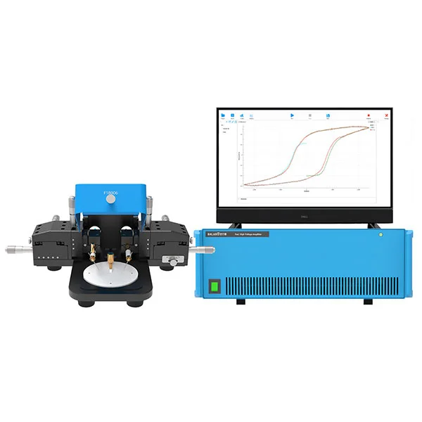
MatMeas FEAI1000 High-Precision Ferroelectric Analyzer
The MatMeas FEAI1000 is an advanced High-Precision Ferroelectric Analyzer specifically engineered for the rigorous evaluation of ferroelectric thin-film materials. Equipped with a built-in or external ±100V high-voltage amplifier, it delivers exceptional accuracy in measuring P-E hysteresis loops, spontaneous polarization, and leakage currents. Designed with proprietary high-voltage breakdown protection, it completely prevents the common catastrophic failures seen in traditional imported models. Offering measurement fidelity that directly rivals the German aixACCT TF2000 and surpassing the PolyK LY20, the FEAI1000 is the ultimate cost-effective infrastructure for dielectric functional ceramics research.
View details →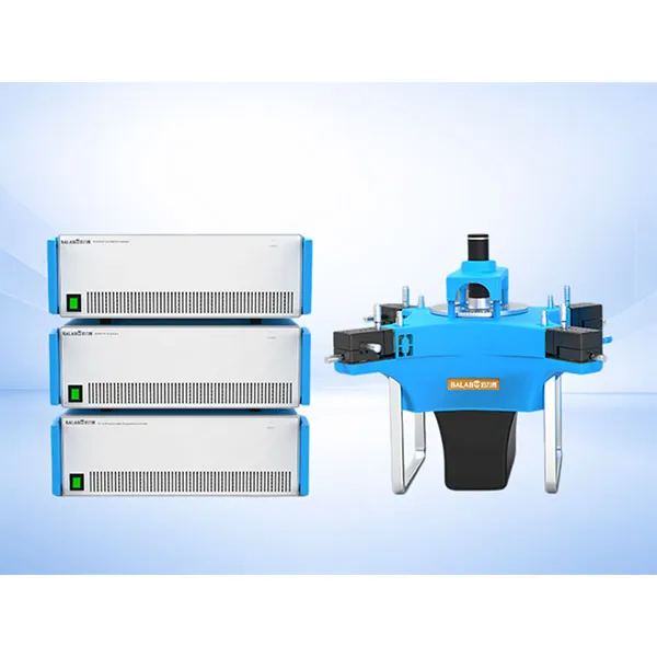
MatMeas FMS Ferroelectric Measurement Spectrometer
MatMeas High‑precision ferroelectric measurement system for hysteresis loop, fatigue testing and leakage current analysis under extreme temperatures.
View details →Request High-Precision Testing Solutions
Get expert guidance and customized instruments for your functional materials project.