The Lifecycle Testing of Piezoelectric Ceramics
Technical News
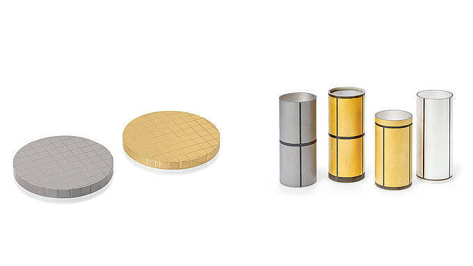
Piezoelectric ceramics—principally lead zirconate titanate (Pb(Zr,Ti)O3 or PZT), modified barium titanate (BaTiO3), and emerging lead-free compositions such as potassium sodium niobate (KNN)—function as the active electromechanical cores of ultrasonic medical imaging arrays, industrial cleaning transducers, sonar systems, and sub-nanometer nanopositioning stages. These devices rely entirely on the reversible, linear conversion of mechanical stress into electrical charge and converse electrical fields into physical displacement.
Achieving high electromechanical yield, narrow resonant frequency distributions, and long-term acoustic stability requires quality control far beyond casual single-point testing. In high-reliability manufacturing, a piezoelectric element undergoes a comprehensive five-stage testing lifecycle: green-body sintering verification, electrode metallization inspection, high-voltage polarization (poling), post-poling aging stabilization, and multi-mode resonance/anti-resonance acceptance screening. Standardized metrology conforming to IEEE Std 176 and IEC 60483 specifications throughout this lifecycle ensures that latent defects—such as micro-cracking, internal electrode delamination, and under-poling—are screened out before component assembly.
The End-to-End Piezoelectric Manufacturing and Quality Lifecycle
Raw sintered ceramics are chemically and crystallographically ferroelectric, yet macroscopically inactive. Within each polycrystalline grain, spontaneous electrical polarization dipoles exist within localized regions called domains. Because thermal sintering ends above the Curie temperature in an unconstrained paraelectric state, cooling through the phase transition forms random domain orientations. The net macroscopic polarization vectors sum to zero (P_net = 0), yielding zero net piezoelectric activity.
Transforming these isotropic ceramic blanks into high-performance electromechanical transducers requires sequential manufacturing and characterization gates:
- Substrate Sintering & Geometry Baseline: Sintered discs or rings must achieve bulk densities exceeding 96% to 98% of theoretical theoretical density. Residual micro-porosity acts as local stress concentrators that cause premature dielectric puncture during subsequent high-voltage poling.
- Electrode Metallization (Silvering / Sputtering): Applying conductive surface layers (typically fired silver paste or sputtered Cr/Au) establishes equipotential boundaries across the element faces.
- High-Voltage Polarization (Poling): Submerging the ceramic in heated dielectric silicone oil while applying intense DC electric fields (typically 2.0 kV/mm to 5.0 kV/mm) permanently rotates switchable ferroelectric domains into alignment with the field vector.
- Thermal Stabilization & Logarithmic Aging: Freshly poled ceramics undergo rapid spontaneous domain wall relaxation. Controlled thermal annealing stabilizes the domain structure, preventing severe in-service calibration drift.
- Full Tensor Resonant Final Screening: Extracting the Butterworth-Van Dyke (BVD) equivalent circuit parameters, resonant/anti-resonant frequencies, and mechanical quality factors verifies finished component quality.
| Manufacturing Stage | Primary Microstructural Defect Monitored | Key Metrological Parameters | Governing Standard | Production Acceptance Benchmark | Dedicated Instrumentation Architecture |
|---|---|---|---|---|---|
| 1. Sintering Inspection | Density variations, sub-surface pores, phase segregation | Bulk Archimedes density, 1 kHz relative permittivity εr | ASTM C373, ASTM D150 | Density ≥ 96.5% theoretical; tanδ ≤ 0.005 | Precision density kit; LCR meter |
| 2. Metallization Firing | Silver adhesion flaws, edge wrap-around flashover paths | Sheet resistance, peel adhesion, edge clearance | ASTM B193, MIL-STD-883 | Sheet resistance ≤ 0.02 Ω/sq; edge margin ≥ 0.5 mm | Four-point probe; optical micrometer |
| 3. High-Voltage Poling | Dielectric breakdown, micro-arcing, thermal runaway | Poling leakage current, saturation current threshold | IEEE Std 176, IEC 60483 | Leakage current < 50 µA/cm^2 @ target E-field | High-voltage oil bath poling system |
| 4. Aging Stabilization | Metastable domain back-switching, internal stress relaxation | Logarithmic aging rate K, 24-hour d33 retention | IEEE Std 176, MIL-STD-1376 | Aging rate K ≤ 1.5% per decade post-stabilization | Standardized thermal soak chamber |
| 5. Resonant Screening | Internal delamination, asymmetrical poling, phase split | Resonance fr, anti-resonance fa, coupling kp, Qm | IEEE Std 176, IEC 60483 | Coupling factor kp within ±2% of nominal target | Precision impedance analyzer |
Physics of High-Voltage Poling: Overcoming Coercive Energy Barriers
During the poling stage, an external electric field E_pol is applied to overcome the coercive field E_c of the ferroelectric material. For hard PZT ceramics (such as PZT-4 and PZT-8), coercive fields range from 1.2 kV/mm to over 2.0 kV/mm at room temperature.
Applying fields of this magnitude in air creates immediate dielectric flashover across the specimen perimeter because the dielectric breakdown strength of ambient air (~3 kV/mm under standard conditions) is lower than the required internal field. To prevent destructive surface arcing, ceramics are poled within a dedicated insulating medium, such as the MatMeas OBP Series high-voltage oil-bath polarization system. High-dielectric-strength silicone oil insulates the specimen perimeter, allowing applied fields exceeding 5 kV/mm to penetrate the ceramic volume safely.
Furthermore, poling is conducted at elevated temperatures (typically 100°C to 150°C, well below the Curie point Tc). Increasing thermal energy lowers the coercive field E_c(T) and accelerates domain wall mobility according to Merz's law:
v = v_inf * exp( -α / E )
where v is domain wall velocity, v_inf is limiting velocity, and α is the thermal activation field. Once domains reorient toward the field direction, the ceramic is cooled back to room temperature with the electric field maintained. This freezes the reoriented dipoles in place, imparting a permanent remanent polarization P_r and strong macroscopic piezoelectricity:
d33 = 2 * Q11 * ε_0 * ε_r * P_r
Unpoled Random Domains (P_net = 0)
           │
           ▼  Heat to 120°C in Silicone Oil (OBP Series)
           │  Apply High DC Field (3 kV/mm > E_c)
           ▼
Forced Domain Alignment (Domain Walls Overcome Pinned Traps)
           │
           ▼  Cool to 25°C under Maintained Electric Field
           ▼  Remove External Voltage
Permanent Remanent Polarization P_r (Active d33, kp, kt Generated)
Post-Poling Logarithmic Aging and Stabilization Kinetics
Immediately after the poling voltage is removed, the newly aligned ferroelectric domain structure is in a metastable thermodynamic state. High localized internal mechanical stresses—induced by anisotropic 90° domain switching—gradually relax through domain back-switching and oxygen vacancy dipole realignment.
This relaxation causes the piezoelectric coefficient (d33), dielectric permittivity (εr), and planar electromechanical coupling factor (kp) to decay logarithmically with time:
d33(t) = d33(t_0) - K * log10( t / t_0 )
where d33(t_0) is the piezoelectric coefficient measured at reference time t_0 (conventionally 1 hour or 24 hours post-poling), t is elapsed operational time, and K is the material aging coefficient (typically 1% to 3% per decade for soft PZT, and < 1% per decade for hard acceptor-doped PZT). Concurrently, the fundamental resonant frequency fr increases slightly as elastic compliance stiffens.
To supply components with guaranteed stability, industrial manufacturers implement accelerated stabilization:
- Thermal Quenching & Baking: Poled elements are baked at 80°C to 120°C for 2 to 4 hours. Thermal acceleration collapses the high-decay early transient regime, advancing the ceramic several decades along the logarithmic aging curve within hours.
- Mechanical Pre-Stress Cycling: Applying cyclic compressive preloads releases trapped domain boundary stresses before calibration.
Full Resonant Impedance Screening and BVD Parameter Extraction
Final quality assurance requires multi-frequency impedance spectroscopy across the fundamental radial, thickness, or longitudinal resonant modes. Conforming to IEEE Std 176 protocols, the MatMeas PCA-1000 piezoelectric characterization analyzer extracts the full Butterworth-Van Dyke (BVD) equivalent circuit parameters:
- Resonant Frequency (fr): The series frequency where electrical impedance drops to its local minimum (
|Z|minimum). - Anti-Resonant Frequency (fa): The parallel frequency where impedance peaks to its maximum (
|Z|maximum).
From fr and fa, the planar electromechanical coupling factor kp for a thin circular disc is calculated using Onoe's transcendental resonance relation:
kp ≈ sqrt[ ( (fa^2 - fr^2) / fa^2 ) * ( (1 - σ^E) / (1 + σ^E) ) ]
where σ^E is the planar Poisson ratio (typically 0.31 to 0.35 for PZT). Simultaneously, the mechanical quality factor Qm is determined:
Qm = fa^2 / [ 2 * π * fr * Z_min * C_0 * (fa^2 - fr^2) ]
A sharp, clean single impedance resonance peak confirms internal structural uniformity. Conversely, dual-split resonance peaks or erratic phase angle dips reveal internal delaminations, micro-cracks, or non-uniform electrode coverage.
For transducers operating under dynamic stress, the MatMeas PEMS-1000 dynamic in-situ measurement system complements resonance screening by evaluating real-time d33 charge generation under continuous dynamic cyclical force sweeps (30 Hz to 300 Hz), validating that the element will survive harsh in-service acoustic fatigue.
| Production Defect Typology | Microstructural Origin | Electrical Signature on Impedance / Metrology | Transducer Failure Impact | Corrective Manufacturing Action |
|---|---|---|---|---|
| Incomplete Poling (Under-Poled) | Field below local coercive threshold Ec; poling oil too cold | Low d33 (30%-50% below spec); low coupling kp; normal fr | Severely diminished acoustic transmission output | Increase poling temperature by 15°C; extend soak time |
| Internal Micro-Cracks | Thermal shock during rapid cooling; excessive poling field | Split resonance peaks (spurious modes); phase angle < 80° | High dielectric loss; premature acoustic fracture | Reduce ramp rates to ≤ 3°C/min; lower poling field |
| Electrode Edge Wrap-Around | Silver paste bleeding over bevel edge | High leakage current (> 100 µA) during poling; spark breakdown | Catastrophic short-circuit; power supply tripping | Adjust screen-printing border margins; laser trim edges |
| Excessive Aging Drift | Donor dopant instability; improper post-pole stabilization | > 5% drop in d33 within 10 days; resonant frequency shift | Sensor calibration drift; acoustic detuning | Implement 100°C 4-hour thermal stabilization bake |
| Low Mechanical Quality (Qm) | Coarse grain boundaries; excessive amorphous secondary phases | Wide, shallow resonance peak; Z_min > 50 Ω (for disc) | Transducer self-heats rapidly; thermal depoling | Optimize sintering firing curve; refine milling purity |
Engineering Best Practices for Production Line Traceability
To maintain consistent acoustic performance across high-volume production:
- Electrode Continuity & Adhesion: Perform scotch-tape peel testing (ASTM D3359) on sample lots post-firing to guarantee metallization adhesion under high-amplitude ultrasonic vibrations.
- Oil Cleanliness: Regularly filter silicone poling oil to remove suspended particulates and moisture, which lower breakdown field thresholds and trigger destructive arc flashover.
- 24-Hour Metric Quarantining: Do not package or ship poled components immediately. Enforce a mandatory 24-hour stabilization hold before conducting final resonance and d33 acceptance grading.
FAQ
Q: Why must piezoelectric ceramics be poled in a dielectric oil bath rather than in air?
A: To force ferroelectric domains into permanent alignment, the applied electric field must exceed the ceramic's coercive field, typically requiring 2.5 kV/mm to 4.0 kV/mm. The dielectric breakdown strength of ambient air is only ~3 kV/mm under ideal conditions, meaning the air around the element will ionize and spark over its edge long before the bulk ceramic can be poled. Submerging the ceramic in high-dielectric-strength silicone oil, as implemented in the MatMeas OBP Series, suppresses surface flashover and directs the high-voltage field safely through the ceramic matrix.
Q: What is the physical origin of the logarithmic aging effect in freshly poled ceramics?
A: During poling, external electric fields force domains to rotate into alignment, generating severe localized anisotropic internal mechanical stresses across adjacent grains. Once the field is removed, these internal mechanical stresses and mobile point defects (such as oxygen vacancy dipoles) gradually relax over time, causing a small fraction of domains to back-switch into lower-energy orientations. This relaxation follows a logarithmic decay law, slowing down with every decade of elapsed time.
Q: How do impedance resonance curves detect internal structural flaws that DC meters miss?
A: DC resistance or low-frequency capacitance measurements only reflect bulk electrical continuity. In contrast, complex impedance spectroscopy dynamically interrogates the mechanical vibration of the entire ceramic body. An internal micro-crack, void, or delamination disrupts acoustic wave propagation across the element, creating parasitic reflections that split the fundamental resonance peak into multiple noisy sub-peaks and suppress the maximum phase angle, instantly identifying flawed components.
Related Instruments & Equipment
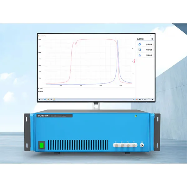
MatMeas High Precision Piezoelectric Ceramic Parameter Analyzer PCA1000
The MatMeas PCA1000 is a domestic-first, cutting-edge Piezoelectric Ceramic Integrated Analyzer engineered to comprehensively evaluate the performance of piezoelectric materials using the advanced AC resonance method. Operating across a wide frequency range from 20Hz to 10MHz with a high measurement accuracy of ±0.05%, it eliminates complex manual calculations by instantly extracting critical data, including electromechanical coupling coefficients (Kp, Kt), mechanical quality factors (Qm), piezoelectric constants (d33, d31, d15), and equivalent circuit models. With intelligent frequency sweeping and visualized data interfaces, the PCA1000 is the ultimate one-stop solution for both rigorous academic research and high-throughput quality screening in industrial mass production.
View details →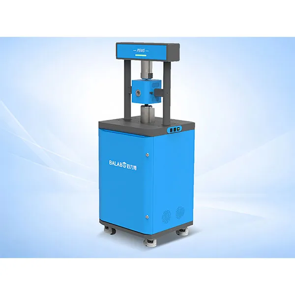
MatMeas High Precision In‑situ d33 Piezoelectric Measurement System – PEMS Analyzer
MatMeas PEMS is a high‑precision in‑situ d33 piezoelectric measurement system for advanced material characterization.
View details →
MatMeas OBP Series High Voltage Piezoelectric Ceramic Polarization
MatMeas OBP Series High Voltage Piezoelectric Ceramic Polarization Instrument is a compact, precise lab device designed for bulk and thin-film materials. It helps achieve optimal polarization effects through process optimization.
View details →Request High-Precision Testing Solutions
Get expert guidance and customized instruments for your functional materials project.