Key Factors Affecting Piezoelectric Ceramic Polarization
Technical News
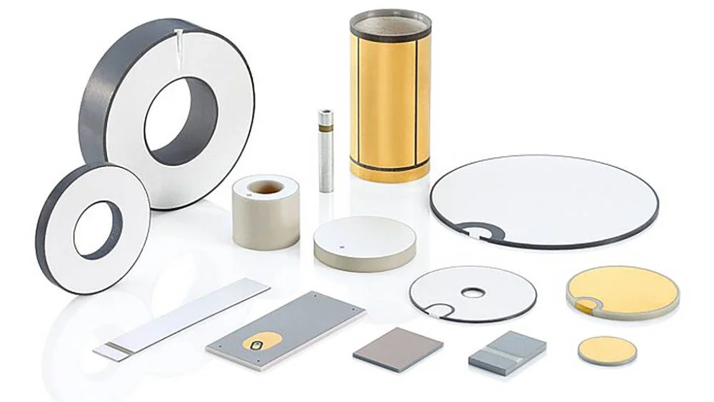
Polarization is the indispensable thermoelectrical processing stage that transforms an isotropic, macroscopically centrosymmetric sintered ferroelectric ceramic into an active piezoelectric transducer component. In as-sintered polycrystalline perovskites such as lead zirconate titanate (PZT), potassium sodium niobate (KNN), and bismuth sodium titanate (BNT), spontaneous polarization vectors within individual crystallographic domains orient randomly along allowed symmetry axes. As a consequence of this structural disorientation, macroscopic dipole moments cancel out entirely, leaving the ceramic devoid of net piezoelectricity.
Achieving a high remanent polarization (Pr) and establishing an optimal longitudinal piezoelectric charge coefficient (d33) requires driving domain wall motion through an externally applied direct current (DC) electric field under controlled thermal excitation. The thermodynamic and physical efficacy of the polarization process is dictated by three interdependent variables: electric field intensity (Ep), polarization temperature (Tp), and polarization dwell duration (tp). Inadequate calibration of these parameters induces severe performance liabilities—ranging from incomplete non-180° domain switching and severe temporal aging decay to catastrophic dielectric punch-through and mechanical micro-cracking.
Core Physical Mechanisms and Constitutive Equations Governing Domain Switching
Ferroelectric domain reorientation in polycrystalline ceramics encompasses two discrete kinetic mechanisms: 180° domain reversal and non-180° (specifically 90° in tetragonal symmetry or 71°/109° in rhombohedral symmetry) ferroelastic switching. While 180° domain reversal occurs purely under electrical driving forces without inducing internal lattice strain, non-180° ferroelastic domain rotation generates massive internal anisotropic mechanical stresses (σij) due to the spontaneous tetragonality (c/a − 1) of the unit cell.
The dynamic evolution of domain switching under an applied external electric field obeys the phenomenological Merz law, which describes switching velocity v as an activated rate process:
v = v∞ · exp(−α / E)
where v∞ denotes the limiting acoustic domain wall velocity, α represents the characteristic activation field, and E is the instantaneous local electric field. To achieve saturated macroscopic polarization across randomly oriented grains, the applied electric field Ep must substantially exceed the intrinsic coercive field (Ec) of the formulation. The temperature-dependent coercive field Ec(T) scales inversely with processing temperature according to empirical power-law thermal relaxation:
Ec(T) = Ec0 · [1 − (T / TC)]β
where TC is the ferroelectric Curie temperature, Ec0 is the cryogenic extrapolation of the coercive field, and β is a material-specific exponent (typically between 0.5 and 0.8 for doped PZT).
Once domain saturation is achieved, the resulting small-signal longitudinal piezoelectric coefficient d33 is fundamentally coupled to the stabilized remanent polarization Pr via the electrostrictive tensor:
d33 = 2 · Q11 · ε0 · εr · Pr
where Q11 represents the longitudinal electrostrictive coefficient, ε0 is the vacuum permittivity (8.854 × 10⁻¹² F/m), and εr is the relative dielectric permittivity of the poled ceramic. Maximizing d33 requires achieving maximum Pr without exceeding the localized dielectric breakdown threshold (Eb) of the intergranular grain boundaries.
Process Parameter Optimization: Hard PZT, Soft PZT, and Lead-Free Systems
Different ceramic compositions possess vastly different domain mobilities, internal defect dipoles, and phase stability limits. Soft donor-doped PZT ceramics (such as PZT-5A) incorporate cation vacancies that unpin domain walls, enabling low coercive fields and facile poling. Conversely, hard acceptor-doped ceramics (such as PZT-4 and PZT-8) feature aligned oxygen-vacancy defect dipoles that create substantial internal bias fields (Ei), requiring elevated poling fields and temperatures to overcome domain pinning. Lead-free compositions exhibit volatile phase boundaries and lower dielectric breakdown margins, demanding narrow thermal windows.
The following process window comparison matrix details established polarization parameters for standard functional ceramics:
| Material Classification | Dominant Phase Symmetry | Curie Temperature TC (°C) | Coercive Field Ec (kV/mm) | Target Poling Field Ep (kV/mm) | Recommended Oil Temp Tp (°C) | Dwell Time tp (min) | Typical Achieved d33 (pC/N) |
|---|---|---|---|---|---|---|---|
| Soft PZT (e.g., PZT-5A / Navy II) | Tetragonal / Rhombohedral MPB | 350–365 | 1.0–1.2 | 3.0–4.0 | 110–130 | 15–20 | 400–480 |
| Hard PZT (e.g., PZT-4 / Navy I) | Rhombohedral MPB | 320–335 | 1.8–2.2 | 4.0–5.5 | 130–150 | 20–30 | 280–330 |
| Super-Hard PZT (e.g., PZT-8 / Navy III) | Tetragonal MPB | 300–315 | 2.2–2.6 | 4.5–6.0 | 140–160 | 25–35 | 215–250 |
| Lead-Free KNN ((K,Na)NbO3) | Orthorhombic / Tetragonal | 380–420 | 1.2–1.5 | 3.5–4.5 | 130–160 | 15–25 | 120–160 |
| Lead-Free BNT-BT (Bi0.5Na0.5TiO3-BaTiO3) | Rhombohedral / Relaxor | 280–310 | 3.0–4.0 | 5.0–6.5 | 60–80 | 10–15 | 150–190 |
International Metrology Standards & Specimen Preparation Protocols
Rigorous polarization and subsequent electromechanical property extraction must adhere to established international standards, predominantly IEEE Std 176 (Standard on Piezoelectricity) and IEC 60483 (Guide to dynamic measurements of piezoelectric ceramics). These standards specify precise sample geometry aspect ratios and surface preparation criteria to prevent premature edge discharge:
- Aspect Ratio and Geometry: For disc geometries intended for radial coupling (kp) and planar evaluation, the diameter-to-thickness ratio (D/t) must exceed 10:1 (typically D = 10–25 mm, t = 0.5–1.0 mm). For longitudinal thickness-mode plates, parallel faces must be lapped to a flatness tolerance within ±1 μm.
- Electrode Integrity & Chamfering: Conductive silver or gold electrodes must terminate cleanly. Edge creeping discharges are suppressed by maintaining an un-metallized annular margin of 0.5 to 1.0 mm along the disc circumference. Sharp perimeter edges must undergo gentle chamfering (45° edge beveling) to prevent localized electrical stress concentration.
- Pre-Poling Annealing: Sintered specimens must undergo thermal annealing at 400°C for 2 hours prior to electroding to relieve residual mechanical stresses accumulated during post-sintering slicing and surface grinding.
Engineering Dielectric Breakdown Prevention and Defect Diagnostics
During high-voltage polarization, ceramics are exposed to electrostatic fields approaching their dielectric breakdown strength. The immersion medium plays an essential dual role: providing dielectric insulation to quench ambient air ionization (which arcs at ~3 kV/mm) and establishing uniform thermal conduction. High-purity methyl silicone oil with a dielectric breakdown strength >15 kV/mm and kinematic viscosity of 50–100 cSt at 25°C is strictly mandated.
The table below outlines the primary industrial failure modes encountered during high-voltage polarization and their root-cause mitigation paths:
| Polarization Failure Mode | Root Physical Mechanism | Detection Diagnostic | Mitigation Protocol |
|---|---|---|---|
| Perimeter Edge Flashover | Air ionization across bare margin or contaminated oil | Visible electric arc tracking; sudden current spike >1 mA | Degas and dehydrate silicone oil at 110°C; expand un-electroded edge margin to 1.0 mm |
| Pinhole Punch-Through | Localized sintering pores or conductive secondary phases | Pinhole puncture with localized electrode vaporization | Optimize ceramic powder calcination; restrict ramping rate to ≤100 V/s |
| Micro-Crack Shattering | Excessive internal mechanical strain from 90° domain switching | Audible snapping; degraded mechanical quality factor Qm | Implement elevated-temperature field ramp; maintain field during slow cooling to <40°C |
| Premature Depoling Aging | Thermal agitation randomizing loosely bound 90° domains | Rapid loss of d33 (>10% drop within 24 hours) | Extend field-cooling dwell; enforce a mandatory 10-day room-temperature aging stabilization |
Hardware Error Mitigation in Automated Multi-Sample Polarization
Achieving reproducibility across high-throughput commercial batches requires eliminating human handling variability and transient electrical transients. The MatMeas MPT Series High Voltage Polarization System addresses these industrial scaling demands by integrating high-voltage programmable power modules (10 kV to 30 kV) across multi-channel fixture configurations accommodating up to 100 ceramic samples simultaneously.

Each channel features individual hardware-level overcurrent trip protection set to 1 mA. If an individual specimen suffers dielectric punch-through, its dedicated fast-acting solid-state switch isolates the defective sample within microseconds, preventing arc propagation or voltage collapse across adjacent parallel channels.
For research laboratories conducting recipe development on specialized geometries, the MatMeas OBP Series Oil Bath Polarization Device provides an ultra-stable, single-sample testbed. Featuring integrated PID thermal regulation up to 180°C and automated safety interlocks with magnetic stirring, the OBP architecture eliminates thermal gradients across thick ceramic elements, ensuring perfectly symmetric domain orientation.
Frequently Asked Questions
What electric field strength is recommended to fully polarize hard PZT versus soft PZT?
Soft PZT compositions (such as PZT-5A) possess low coercive fields (Ec ≈ 1.0–1.2 kV/mm) due to cation-vacancy domain unpinning, requiring a polarization field of 3.0 to 4.0 kV/mm at 110°C–130°C. Hard PZT formulations (such as PZT-4 and PZT-8) contain acceptor dopants that pin domain walls with defect dipoles (Ec ≈ 1.8–2.6 kV/mm); they demand higher poling fields of 4.5 to 6.0 kV/mm applied at 140°C–160°C to achieve complete ferroelectric domain saturation.
Why must the high-voltage electric field be maintained during the cooling phase?
Ferroelectric domain switching involves overcoming an energetic barrier. When domains align at elevated temperatures (Tp), thermal fluctuations remain high. If the electric field is removed while the ceramic is still hot, thermal agitation immediately randomizes a significant fraction of non-180° domains back toward lower-strain configurations. Maintaining the electric field continuously until the silicone oil bath cools below 40°C freezes the aligned domains securely within their crystal lattices, maximizing remanent polarization.
How does silicone oil quality influence polarization yield and dielectric safety?
Silicone oil serves as the primary external dielectric barrier preventing atmospheric surface flashover around the ceramic edges. If the oil absorbs atmospheric moisture or becomes contaminated with carbonized debris from previous dielectric breakdowns, its dielectric strength drops drastically below 10 kV/mm. This initiates edge tracking discharges well below the intrinsic breakdown voltage of the ceramic. Regular oil dehydration, particulate filtration, and periodic fluid replacement are essential to maintain high production yields.
Related Instruments & Equipment
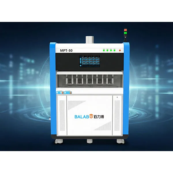
MatMeas Automatic High Voltage Polarization System for Piezoelectric Ceramics – MPT Series
The MatMeas MPT Series is an intelligent, fully automated high-voltage polarizer designed for the high-yield mass production and advanced research of piezoelectric ceramics. Capable of simultaneously polarizing up to 100 samples in an oil-bath environment, each independent channel delivers up to 30kV and 1mA without mutual interference. Featuring an intelligent self-diagnostic safety check, comprehensive data traceability, and precision PID temperature control up to 180°C, the MPT Series guarantees consistent, high-yield poling results without manual supervision. It is the trusted polarization infrastructure for industry leaders like Huawei Technologies and the China Institute of Atomic Energy (CIAE).
View details →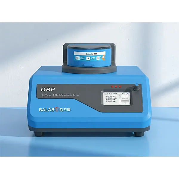
MatMeas OBP Series High Voltage Piezoelectric Ceramic Polarization
MatMeas OBP Series High Voltage Piezoelectric Ceramic Polarization Instrument is a compact, precise lab device designed for bulk and thin-film materials. It helps achieve optimal polarization effects through process optimization.
View details →Request High-Precision Testing Solutions
Get expert guidance and customized instruments for your functional materials project.