Thermally Stimulated Depolarization Current (TSDC) Testing
Technical News
Thermally Stimulated Depolarization Current (TSDC)—also recognized in solid-state physics as Thermally Stimulated Discharge Current or Ionic Thermocurrent (ITC)—represents the most sensitive and spectrally resolving analytical metrology for investigating localized dipole relaxation, space charge accumulation, and deep-level defect trap energy distributions in insulating dielectrics, functional electroceramics, and wide-bandgap semiconductors.
While conventional Broadband Dielectric Spectroscopy (BDS) measures the steady-state alternating-current (AC) response of a material at constant temperature across frequency decades, BDS is fundamentally limited by high-temperature ohmic conduction, which swamps ultra-slow dipolar relaxation processes. TSDC bypasses this limitation by freezing dipolar and trapped space charge states at cryogenic temperatures under intense DC electric bias, subsequently monitoring their spontaneous release as sub-picoampere (pA to fA) short-circuit currents during a strictly linear thermal ramp. Grounded in ASTM D257 and IEC 60093 principles, TSDC enables materials scientists to map carrier trap depths from 0.2 eV to well over 2.5 eV, providing critical insights into dielectric breakdown prevention, energy storage polymer aging, and semiconductor reliability.
The Physical Framework of TSDC: Polarize, Freeze, and Thermally Stimulate
The physical mechanism of TSDC is governed by non-isothermal charge relaxation kinetics across four distinct experimental regimes:
- High-Temperature Polarization (Tp, Ep): The dielectric specimen is heated to an activation temperature
T_pwhere molecular segments, intrinsic dipole moments, and charge carriers possess high thermal mobility. A high DC electric fieldE_p(typically 10 kV/cm to 500 kV/cm) is applied for a polarization durationt_p(10 to 30 minutes). Mobile dipoles rotate into alignment with the field vector, while free electrons, holes, or ionic vacancies drift and become captured in localized structural energy wells (defect traps). - Cryogenic Quenching (T0): While maintaining the full DC electric field
E_p, the specimen is rapidly quenched to deep cryogenic temperaturesT_0(typically 77K to -160°C via liquid nitrogen cooling). Rapid cooling dramatically prolongs the dielectric relaxation time constant (τ), effectively "freezing" the aligned dipoles and trapped space charges in their non-equilibrium oriented configuration. - Short-Circuit Depolarization: Once thermal equilibrium is reached at
T_0, the external electric field is switched off, and the electrodes are short-circuited through an ultra-high-resolution electrometer for a brief dwell period (5 to 10 minutes). This allows fast capacitive displacement charges and shallow surface charges to discharge completely. - Linear Thermal Stimulation (β): The specimen is heated at an ultra-stable, strictly linear heating rate:
T(t) = T_0 + β * t
where β = dT/dt is the heating rate (conventionally 1°C/min to 5°C/min). As thermal energy increases, frozen dipoles and trapped charges sequentially overcome their localized potential energy barriers. As dipoles randomize and detrapped carriers drift under internal space-charge fields toward the electrodes, a minute depolarization current flows through the external electrometer, tracing a spectrum of distinct current peaks as a function of temperature.
High-Temp Polarization (Tp, Ep) ──> Cryogenic Quench to T0 (Ep On)
                                             │
                                             ▼
                                  Zero-Volt Short Circuit
                                             │
                                             ▼
               Linear Heating Ramp (β = dT/dt) with Femtoammeter
                                             │
                                             ▼
                     TSDC Spectrum Peak Analysis J(T) vs. T
Mathematical Modeling: The Bucci-Fieschi-Guidi (BFG) Constitutive Equation
For a discrete, single-relaxation dipolar process obeying first-order Arrhenius kinetics, the temperature-dependent relaxation time constant τ(T) follows:
τ(T) = τ_0 * exp[ E_a / ( k_B * T ) ]
where τ_0 is the characteristic attempt-to-escape relaxation time (typically 10^-12 to 10^-14 seconds for molecular dipoles), E_a is the activation energy of the trap or dipole barrier in electron-volts, k_B is the Boltzmann constant (8.617 * 10^-5 eV/K), and T is absolute temperature in Kelvin.
Bucci, Fieschi, and Guidi derived the analytical constitutive equation describing the released depolarization current density J(T) during a linear thermal ramp:
J(T) = ( P_0 / τ_0 ) * exp( -E_a / ( k_B * T ) ) * exp[ - ( 1 / ( β * τ_0 ) ) * ∫_{T_0}^T exp( -E_a / ( k_B * T' ) ) dT' ]
where P_0 is the initial saturated polarization induced at T_p.
The mathematical profile of J(T) exhibits an asymmetric bell shape:
- Initial Exponential Surge: At low temperatures (
T << T_m), the second exponential term (the integral integral) remains close to unity. The depolarization current surges exponentially, governed strictly byexp(-E_a / (k_B * T)). - Current Maximum (T_m): The current reaches its maximum peak at temperature
T_m, satisfying the conditiondJ/dT = 0:
T_m = [ ( β * E_a * τ(T_m) ) / k_B ]^(1/2)
- Exhaustion Collapse: Above
T_m, the rapid exhaustion of polarized dipoles drives the integral term toward zero, causing the current to collapse precipitously back to baseline.
To extract the activation energy E_a without making assumptions regarding the attempt frequency 1/τ_0, engineers deploy the Garlick-Gibson Initial Rise Method. For the initial 10% to 15% of the rising current edge (T < T_m), the integral term is negligible, reducing the equation to:
ln[ J(T) ] ≈ Constant - ( E_a / ( k_B * T ) )
By plotting ln[J(T)] against 1/T, the activation energy E_a is extracted directly from the slope (-E_a / k_B), providing absolute calibration independent of peak shape.
The total trapped charge density Q_total released across the relaxation peak is determined by integrating the current over time:
Q_total = ( 1 / β ) * ∫_{T_initial}^{T_final} J(T) dT
| Trap Characterization Technique | Underlying Excitation Domain | Measured Primary Observable | Energy Trap Depth Window (eV) | Minimum Current / Charge Sensitivity | Primary Analytical Advantage | Core Metrological Limitation |
|---|---|---|---|---|---|---|
| TSDC (Thermally Stimulated) | Non-isothermal DC thermal ramp | Thermally released short-circuit current (fA - pA) | 0.2 eV to > 2.5 eV | 10^-15 A (1 fA) / ~10^-14 C | Resolves ultra-slow deep traps; eliminates ohmic masking | Non-isothermal sweep; thermal lag artifacts if uncalibrated |
| BDS (Dielectric Spectroscopy) | Isothermal AC frequency sweep (µHz - GHz) | Complex permittivity ε*, loss factor tanδ | 0.1 eV to 1.0 eV | tanδ ~ 10^-5 | High frequency range; captures rapid dipolar rotations | Deep traps masked by DC conduction at high temperatures |
| DLTS (Deep Level Transient) | Isothermal pulsed voltage in p-n / Schottky | High-frequency capacitance transient ΔC(t) | 0.05 eV to 1.2 eV | Trap density ~ 10^10 cm^-3 | Absolute trap cross-section extraction | Restricted to conducting semiconductor junctions |
| PEA (Pulsed Electroacoustic) | High-voltage nanosecond acoustic pulse | Acoustic pressure wave amplitude & acoustic transit | Macroscopic spatial profiles | Space charge > 10^-3 C/m^3 | Spatially resolves space charge depth distribution | Low energy resolution; insensitive to sub-micron traps |
Benchmark TSDC Spectra Across Functional Material Classes
TSDC spectroscopy distinguishes between intrinsic dipolar rotations (e.g., polymer sub-glass transitions) and extrinsic space-charge detrapping (e.g., oxygen vacancy migration in electroceramics).
| Material System | Chemical Matrix / Form | Identified Relaxation Peak | Peak Temp Tm (°C) | Trap Activation Energy Ea (eV) | Natural Relaxation Time τ0 (s) | Microstructural Defect Origin |
|---|---|---|---|---|---|---|
| XLPE (Crosslinked Polyethylene) | High-voltage cable grade insulation | β-relaxation (Side chain) / α-relaxation (Crystalline) / ρ-peak (Space charge) | -120°C to -100°C / 45°C to 65°C / 95°C to 110°C | 0.35 - 0.45 / 0.85 - 1.05 / 1.25 - 1.45 | 10^-13 / 10^-14 / 10^-12 | Carbonyl impurity dipoles / Lamellar boundary slip / Crosslinking peroxide residue traps |
| Polyimide (PI Film) | High-temperature capacitor dielectric | β-relaxation (Dipolar) / γ-peak (Space charge) | 70°C to 90°C / 240°C to 280°C | 0.75 - 0.90 / 1.60 - 1.95 | 10^-13 / 10^-12 | Imide ring orientation / Electrode-injected interfacial electrons |
| P(VDF-TrFE) 70/30 | Ferroelectric copolymer film | β-relaxation (Glass transition) / Curie transition (Depoling) | -35°C to -25°C / 105°C to 115°C | 0.50 - 0.65 / 2.10 - 2.80 | 10^-12 / 10^-15 | Amorphous chain segments / Ferroelectric domain dipole reversal |
| BaTiO3 (MLCC Ceramic) | Rare-earth doped perovskite | Depolarization peak / Ionic conduction peak | 125°C to 130°C / 280°C to 340°C | 0.95 - 1.15 / 1.35 - 1.65 | 10^-14 / 10^-13 | Spontaneous polarization collapse / Doubly ionized oxygen vacancies V_O^•• |
| GaN Epilayer on Sapphire | Wide-bandgap semiconductor | Defect trap detrapping | 150°C to 220°C | 0.60 - 0.85 | 10^-11 | Nitrogen vacancies and threading dislocations |
Overcoming Metrological Roadblocks in Femtoampere (fA) Detection
Measuring TSDC currents—which routinely peak below 10^-12 A (1 pA) and approach 10^-15 A (1 fA) in high-purity dielectrics—presents severe experimental vulnerabilities that render standard benchtop test chambers completely inadequate:
- Triboelectric Cable Friction and Microphonics: When coaxial cables experience mechanical vibrations or thermal contraction, friction between the inner polyethylene/PTFE dielectric and outer braided shielding generates spurious triboelectric currents exceeding 50 fA to 500 fA. Overcoming this requires rigid, solid-shielded triaxial cabling featuring graphite-lubricated semi-conductive layers.
- Atmospheric Moisture Condensation (False Water Peaks): Cooling samples down to cryogenic baselines (-160°C) in ambient air causes water vapor to freeze across the electrode edges. During subsequent linear heating, the phase transition of ice near 0°C generates massive spurious current spikes (hundreds of picoamperes) that completely obliterate true defect relaxation peaks.
- Mechanical Probe Contact Vibration: Thermal expansion during rapid ramps can shift micro-probe arms across sub-millimeter thin-film pads, breaking electrical contact or creating micro-arcing noise spikes.
Precision In-Situ Metrology via Vacuum Micro-Probing
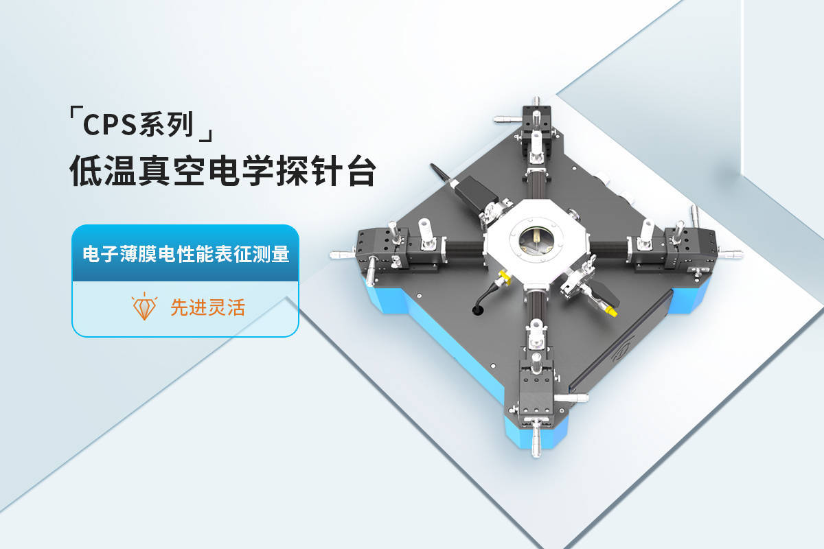
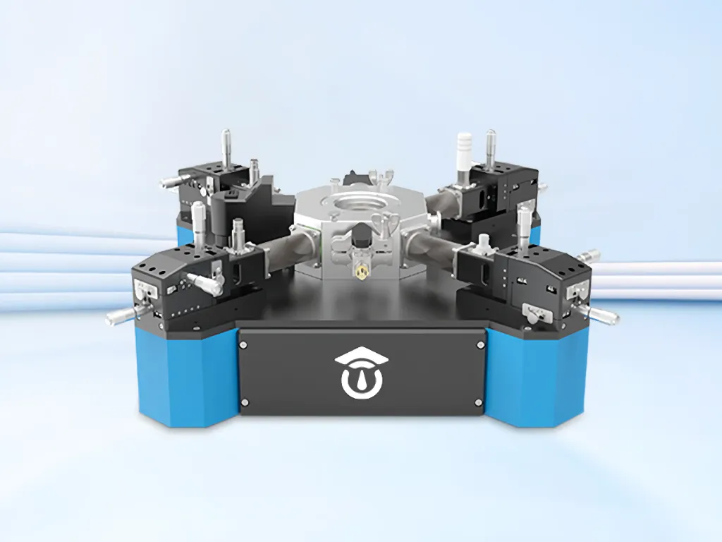
To isolate pure volumetric depolarization currents from external noise, advanced characterization platforms integrate deep-vacuum sample isolation with pneumatic vibration damping. The MatMeas CPS-7000 high-low temperature dielectric vacuum probe station is engineered specifically for sub-picoampere TSDC protocols.
By evacuating the testing chamber to a high vacuum (< 10^-2 Pa) prior to cryogenic cooling via controlled liquid nitrogen circulation, the MatMeas CPS-7000 completely eliminates atmospheric moisture, guaranteeing 100% frost-free, artifact-free TSDC spectra from -160°C up to 450°C. To prevent mechanical microphonics from corrupting femtoampere baselines, the CPS-7000 integrates a built-in pneumatic shock-absorption and vibration isolation system directly within the chassis, decoupling the probing stage from building vibrations without requiring bulky optical tables.
Furthermore, the system's low-thermal-mass sample chuck is driven by a precision PID temperature controller that enforces linear heating ramp rates (programmable from 0.5°C/min to 10°C/min) with thermal linearity deviation bounded within ±0.1°C, ensuring high analytical accuracy during Bucci-Fieschi-Guidi curve fitting. Four independently manipulated micro-probing arms featuring triaxial driven guards eliminate parasitic leakage to ground, ensuring that sensitive electrometers capture only intrinsic bulk detrapping currents.
FAQ
Q: Why can TSDC detect deep-level defect states that Broadband Dielectric Spectroscopy (BDS) cannot resolve?
A: In Broadband Dielectric Spectroscopy at elevated temperatures, thermally activated DC electrical conduction (ohmic conduction through mobile charge carriers) escalates exponentially. This massive conduction current swamps the imaginary permittivity (loss factor ε''), burying weak, slow dipolar relaxation peaks. TSDC avoids this by freezing polarization at low temperatures and measuring current in an externally short-circuited state without an applied voltage, completely eliminating DC ohmic conduction and exposing pure, isolated detrapping peaks with femtoampere sensitivity.
Q: How does the Initial Rise method extract trap activation energy without knowing the relaxation frequency?
A: The Garlick-Gibson Initial Rise method takes advantage of the fact that during the first 10% to 15% of the rising edge of a TSDC current peak, the number of emptied traps is negligible compared to the total population of frozen traps. In this initial thermal regime, the exhaustion integral term in the Bucci-Fieschi-Guidi equation equals approximately 1.0. Consequently, the current depends solely on the Arrhenius term exp(-Ea / kBT). Plotting ln(J) versus 1/T yields a linear slope of -Ea / kB, calculating the activation energy Ea directly without requiring knowledge of the attempt frequency factor τ0.
Q: What is the purpose of the cryogenic thermal soak in a TSDC experimental protocol?
A: The cryogenic soak (typically at -160°C or 77K) freezes the aligned dipoles and trapped space charges in their non-equilibrium orientation by maximizing the relaxation time constant τ. Removing the high-voltage poling field during this cryogenic dwell permits fast geometric and capacitive displacement currents to discharge completely through the electrometer while internal dipoles remain firmly locked in place. This guarantees that subsequent current peaks measured during linear heating represent genuine thermally stimulated depolarization rather than lingering external circuit transients.
Request High-Precision Testing Solutions
Get expert guidance and customized instruments for your functional materials project.