Ceramic Substrate Relative Permittivity Testing: Principles and Methods
Technical News
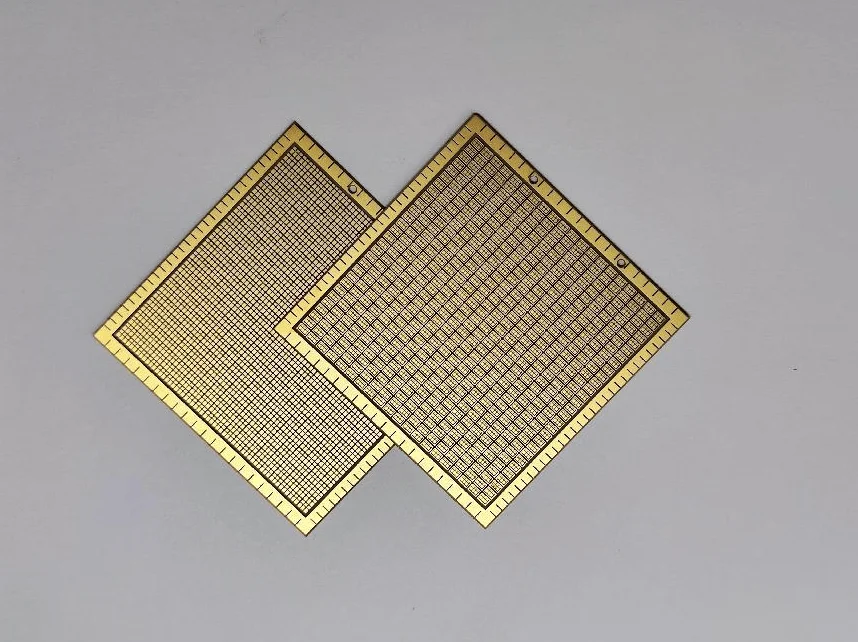
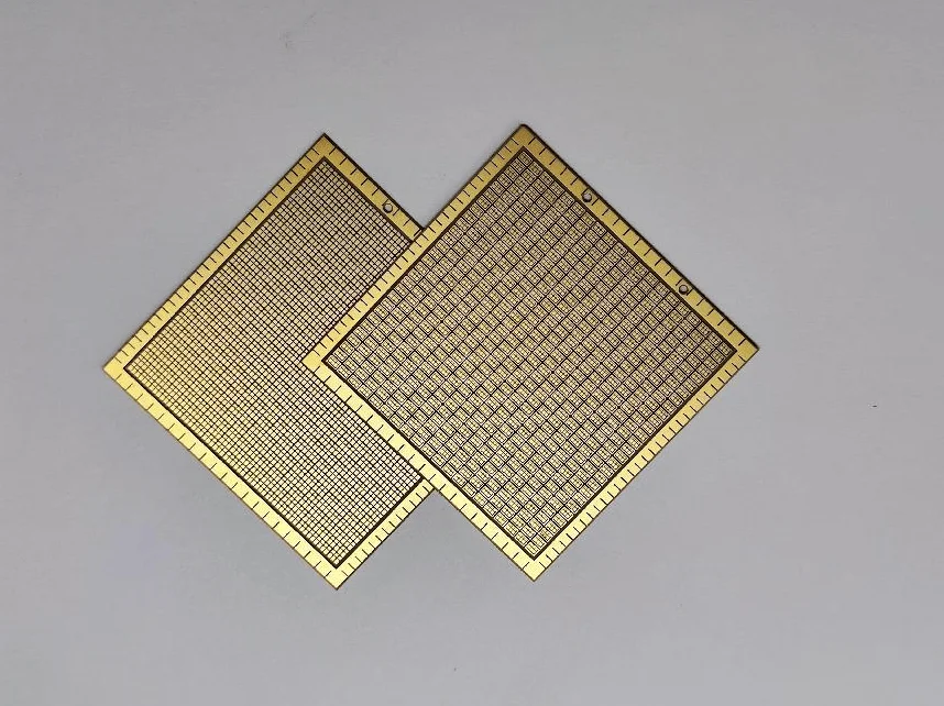
In modern radio frequency (RF) microelectronics, wide-bandgap power semiconductor packaging, and microwave telecommunications, ceramic substrates provide structural rigidity, heat dissipation, and electrical isolation. A foundational electrodynamic metric governing their high-frequency signal integrity is relative permittivity (dielectric constant, εr). Relative permittivity defines a material's capacity to store electrostatic potential energy under an alternating electric field, directly dictating capacitive coupling, electromagnetic wave velocity, characteristic impedance matching, and transmission loss.
Selecting the appropriate measurement methodology is vital to ensure that substrate characterization accurately reflects the operational frequencies, geometric configurations, and thermal gradients encountered in actual electronic hardware.
Fundamentals of Relative Permittivity in Ceramic Substrates
Relative permittivity represents the ratio of electrostatic permittivity of a ceramic medium (ε) to the permittivity of free space (ε_0 = 8.854 * 10^-12 F/m), as characterized in our ceramic substrate dielectric constant testing guide:
ε_r = ε / ε_0
When exposed to an alternating electric field, microscopic charges inside the ceramic matrix displace, inducing internal electronic, ionic, and dipolar polarization while dissipating energy as detailed in our guide on ceramic substrate dielectric loss testing:
- Capacitive Energy Storage: Higher relative permittivity allows increased electrical charge accumulation across a given voltage gradient. In energy-storage multi-layer capacitors and antenna substrates, elevated permittivity facilitates miniaturization.
- Electromagnetic Wave Velocity and Propagation: Signal propagation velocity (
v_p) along a planar microstrip line scales inversely with the square root of effective relative permittivity:
v_p = c / sqrt( ε_eff )
λ_g = λ_0 / sqrt( ε_eff )
where c is the speed of light in vacuum and λ_g is the guided wavelength. In high-frequency transmission lines, elevated permittivity shortens guided wavelengths, promoting compact layout geometry while demanding tighter line-width fabrication tolerances.
3. Impedance Discontinuities: In 50 Ω planar interconnects, variations in substrate permittivity alter line capacitance per unit length, creating reflection coefficients that degrade return loss and elevate bit error rates.
Comparison of Relative Permittivity Measurement Techniques
Characterizing dielectric constant across wide frequency spectra requires choosing measurement topologies matched to specific frequency bands and sample geometries, particularly when validating high frequency ceramic substrate permittivity for RF electronics.
| Measurement Methodology | Governing Standard | Frequency Coverage | Relative Permittivity Uncertainty | Loss Tangent Resolution | Electrode Metallization | Thermal Sweep Feasibility | Primary Metrological Fit |
|---|---|---|---|---|---|---|---|
| Parallel-Plate Capacitance | ASTM D150 / IEC 60250 | 20 Hz to 30 MHz | ±0.5% to ±1.0% | 1.0 * 10^-4 | Required (sputtered or painted noble metal) | Excellent (-160°C to 1000°C) | Continuous broadband frequency sweeps, defect relaxation, temperature coefficients |
| Split-Post Dielectric Resonator (SPDR) | IEC 61189-2-721 | 1 GHz to 20 GHz (Fixed) | ±0.5% to ±1.5% | 2.0 * 10^-5 | Non-metallized (bare planar substrate) | Limited (ambient to 85°C) | Ultra-precise microwave permittivity and low loss tangent screening of planar sheets |
| Resonant Cavity Perturbation | ASTM D2520 | 1 GHz to 35 GHz (Discrete) | ±1.0% to ±2.0% | 1.0 * 10^-4 | Non-metallized (small rod or capillary) | Moderate (-50°C to 300°C) | High-temperature microwave ceramic evaluation, isotropic dielectric rods |
| Microstrip Differential Length | IPC-TM-650 2.5.5.5 | 1 GHz to 40 GHz (Broadband) | ±2.0% to ±4.0% | 5.0 * 10^-3 | Patterned microstrip transmission traces | Moderate (controlled hot-plate) | Design validation of fabricated RF circuit boards; includes conductor loss |
While parallel-plate impedance spectroscopy excels at continuous frequency sweeps and extreme temperature tracking, microwave resonant cavity methods provide electrode-free loss tangent characterization at gigahertz frequencies.
Benchmark of Electronic and Microwave Ceramic Substrates
Substrate selection requires balancing dielectric permittivity, dielectric loss, thermal expansion, and temperature stability.
| Substrate Material | Grade / Purity | Relative Permittivity εr (1 MHz) | Relative Permittivity εr (10 GHz) | Loss Tangent tan δ (10 GHz) | Temp Coefficient TCε (ppm/K) | Thermal Conductivity k (W/m·K) | Target Microwave Application |
|---|---|---|---|---|---|---|---|
| 96% Al2O3 | Electronic Thick-Film Grade | 9.5 - 9.8 | 9.3 - 9.6 | 0.0012 - 0.0025 | +120 to +160 | 20 - 24 | Automotive power modules, industrial control circuitry |
| 99.6% Al2O3 | Polished Thin-Film Grade | 9.8 - 10.0 | 9.7 - 9.9 | 0.0001 - 0.0004 | +100 to +130 | 28 - 32 | High-density microwave hybrid circuits, satellite transceivers |
| AlN (Aluminum Nitride) | High Thermal Conductivity | 8.7 - 9.0 | 8.6 - 8.9 | 0.0005 - 0.0010 | +80 to +110 | 170 - 200 | High-power RF amplifiers, laser diode submounts, SiC modules |
| Si3N4 (Silicon Nitride) | Active Metal Brazed (AMB) | 8.2 - 8.5 | 8.1 - 8.4 | 0.0025 - 0.0045 | +60 to +90 | 80 - 90 | High-stress electric vehicle inverters, wind turbine modules |
| LTCC Glass-Ceramic | Low-Loss High-Frequency | 6.2 - 7.5 | 6.0 - 7.3 | 0.0015 - 0.0030 | -50 to +50 | 3 - 5 | Multi-layer 5G front-end modules, phased array antennas |
| Fused Silica (SiO2) | Optical / RF Grade | 3.8 - 3.9 | 3.8 - 3.85 | 0.0001 - 0.0002 | +15 to +30 | 1.4 - 1.6 | 77 GHz automotive radar, spaceborne communication radomes |
High-purity 99.6% alumina combines high permittivity with ultra-low loss for thin-film circuits, whereas aluminum nitride delivers high thermal conductivity with moderate permittivity for high-power semiconductor packaging.
Parallel-Plate Capacitance Metrology and Edge Fringing Corrections
In the parallel-plate configuration conforming to ASTM D150, measured capacitance C_p is converted into relative permittivity:
C_p = ε_0 * ε_r * ( A / t )
where A is electrode area and t is specimen thickness. When using un-guarded two-terminal electrodes, electric field lines bulge at the electrode perimeter, creating edge fringing capacitance (C_e) that inflates apparent permittivity:
C_measured = C_geometric + C_e
ASTM D150 and Kirchhoff formulations correct for edge fringing on circular electrodes without a guard ring:
C_e = ( 0.0019 * ε_r - 0.00252 * ln(t) + 0.0068 ) * P
where P is electrode perimeter in centimeters and t is thickness in centimeters. To completely eliminate fringing field distortion, standardized metrology utilizes a three-terminal guarded electrode geometry. The effective area A_eff is computed across the central electrode diameter d1 and guard ring gap g:
A_eff = ( π / 4 ) * ( d1 + g )^2
ε_r = ( C_p * t ) / ( ε_0 * A_eff )
Resonant Cavity Perturbation Mechanics
At gigahertz frequencies, contact lead inductances distort parallel-plate measurements. Resonant cavity perturbation (ASTM D2520) inserts a small, non-metallized ceramic specimen into a high-Q electromagnetic cavity resonator. The specimen perturbs the internal field, shifting the resonant frequency from f_0 to f_s and broadening the half-power bandwidth from BW_0 to BW_s:
( f_0 - f_s ) / f_0 = 0.5 * ( ε_r - 1 ) * ( V_sample / V_cavity ) * F_geom
1 / Q_s - 1 / Q_0 = ε_r * tan δ * ( V_sample / V_cavity ) * F_geom
where V_sample and V_cavity are specimen and cavity volumes, and F_geom is a field-filling geometric form factor. This enables contactless extraction of permittivity and loss tangent without metallization artifacts.
High-Temperature Dielectric Characterization with MatMeas DMS-1000
Ceramic substrates in power electronic modules and aerospace sensors endure severe thermal gradients. Tracking permittivity shifts as a function of temperature is vital for thermal stability verification.
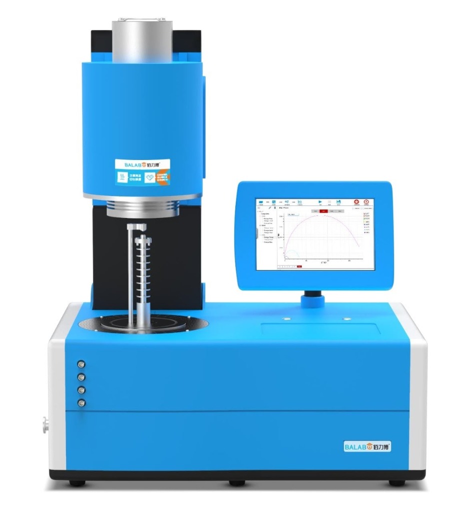
The MatMeas DMS-1000 high-temperature dielectric measurement system provides automated impedance and relative permittivity characterization across wide thermal and frequency regimes.
Key technical capabilities of the DMS-1000 include:
- Broad Thermal Range (Ambient to 1000°C): High-precision PID furnace regulation maintains ±0.5°C stability, enabling continuous evaluation of thermal permittivity drift and phase transitions.
- Wide Frequency Bandwidth (20 Hz to 30 MHz): High-resolution impedance testing with 0.05% basic measurement accuracy for broadband characterization.
- High-Purity Platinum Fixtures: Equipped with platinum three-terminal guarded electrodes, ensuring stable, non-oxidizing electrical contact across high-temperature sweeps.
- Controlled Atmospheres: Supports testing in air, inert gases (nitrogen, argon), reducing atmospheres, and high vacuum to replicate real operating environments.
- Calibrated Contact Loading: Features calibrated spring-loaded fixturing that accommodates ceramic discs and plates up to 20 mm in diameter and 5 mm thickness without mechanical fracture.
Frequently Asked Questions
Why do permittivity measurements differ between parallel-plate and resonant cavity methods?
Parallel-plate capacitance methods operate between 20 Hz and 30 MHz with contact electrodes applied to the sample, making them sensitive to electrode contact quality and interfacial air gaps. Resonant cavity methods operate at discrete gigahertz frequencies without electrodes, evaluating purely electromagnetic perturbation. Differences in test frequency, dielectric dispersion, and polarization mechanisms naturally yield slightly different permittivity values between the two methods.
How does temperature elevation affect the relative permittivity of ceramic substrates?
In non-ferroelectric ceramic substrates, elevated temperature increases lattice expansion and ionic polarizability, typically yielding a gradual, positive Temperature Coefficient of Permittivity (TCε between +50 and +160 ppm/K). In ferroelectric materials, permittivity rises sharply toward a peak at the Curie transition temperature. The MatMeas DMS-1000 tracks these shifts continuously up to 1000°C.
What specimen preparation is required for parallel-plate relative permittivity testing?
Parallel-plate testing requires flat, polished ceramic substrate samples with strictly parallel opposing faces. Conductive metal electrodes (typically platinum, gold, or silver) are deposited onto both sides to eliminate parasitic air gaps. In high-temperature testing up to 1000°C, noble platinum electrodes and guarded fixtures are mandatory to prevent electrode oxidation and edge fringing errors.
Request High-Precision Testing Solutions
Get expert guidance and customized instruments for your functional materials project.