MLCC Capacitor Electrical Performance Testing
Technical News
Multilayer Ceramic Capacitors (MLCCs) represent the most extensively manufactured passive electronic component in the global semiconductor supply chain, with annual production surpassing several trillion units. From high-speed server motherboards, graphics processing units (GPUs), and 5G cellular modems to automotive Advanced Driver Assistance Systems (ADAS) and electric vehicle (EV) traction inverters, MLCCs perform indispensable circuit functions: DC decoupling, high-frequency noise filtering, AC signal coupling, and localized energy storage.
Over recent design generations, relentless packaging miniaturization (down to 0201 and 01005 imperial footprints) coupled with explosive demands for high volumetric capacitance has driven dielectric layer thicknesses down to sub-micron regimes (< 1 micrometer), with layer counts exceeding 1,000 per chip. Operating in close proximity to high-current silicon switches subjects these ultra-thin ceramic films to severe electrical fields (> 50 kV/mm) and extreme thermal cycling (-55°C to 150°C). Consequently, comprehensive electrical testing—encompassing equivalent series resistance (ESR), DC bias derating, insulation resistance (IR), dielectric withstanding voltage (DWV), and Highly Accelerated Life Testing (HALT)—is mandatory to safeguard mission-critical systems against catastrophic in-service short circuits.
Dielectric Classification and Temperature Coefficient of Capacitance
The electrical performance of an MLCC is fundamentally dictated by its ceramic dielectric chemistry, categorized under Electronic Industries Alliance (EIA-198) and IEC 60384 specifications into distinct classes:
- Class I Dielectrics (Ultra-Stable, Paraelectric): Formulated from temperature-compensated paraelectric oxides such as calcium zirconate (CaZrO3), neodymium titanate, or modified TiO2. Characterized by low relative permittivity (εr between 20 and 100), Class I capacitors—exemplified by C0G/NP0 formulations—exhibit near-zero temperature drift across -55°C to +125°C (drift bounded within 0 ± 30 ppm/°C). They exhibit no ferroelectric hysteresis, zero DC bias voltage degradation, negligible aging, and ultra-low dielectric dissipation factors (tanδ < 0.001), rendering them the definitive choice for precision RF matching, resonant tank circuits, and high-stability timing oscillators.
- Class II and Class III Dielectrics (High-Permittivity, Ferroelectric): Based on modified barium titanate (BaTiO3) perovskite ceramics. By operating near the ferroelectric-to-paraelectric transition, Class II ceramics achieve massive relative permittivities (εr spanning 1,500 to over 5,000), enabling microfarad-level capacitances in compact packages. However, the presence of switchable ferroelectric domains introduces substantial trade-offs: non-linear capacitance degradation under applied DC bias, elevated dissipation factors (tanδ between 0.015 and 0.050), and pronounced temperature-dependent capacitance shifts (TCC).
| EIA Dielectric Code | Dielectric Classification | Base Ceramic Matrix | Operational Temperature Range (°C) | Maximum Capacitance Drift ΔC/C (%) | Typical Dissipation Factor tanδ (max @ 1 kHz) | DC Bias Derating @ Rated Voltage | Primary Application Field |
|---|---|---|---|---|---|---|---|
| C0G (NP0) | Class I Paraelectric | Modified CaZrO3 / TiO2 | -55°C to +125°C | ±30 ppm/°C (±0.3% max) | ≤ 0.0010 (0.10%) | 0% (No DC bias decay) | RF front-ends, high-Q resonators, PLL timing |
| X5R | Class II Ferroelectric | Modified BaTiO3 | -55°C to +85°C | ±15% | ≤ 0.0500 (5.00%) | -40% to -70% capacitance loss | Consumer mobile devices, general DC decoupling |
| X7R | Class II Ferroelectric | Doped BaTiO3 (Rare-earth core-shell) | -55°C to +125°C | ±15% | ≤ 0.0250 (2.50%) | -30% to -60% capacitance loss | Industrial computing, automotive body electronics |
| X8R | Class II Ferroelectric | High-temperature BaTiO3-BiScO3 | -55°C to +150°C | ±15% | ≤ 0.0250 (2.50%) | -35% to -65% capacitance loss | Under-hood automotive powertrain, downhole tools |
| Y5V | Class III Ferroelectric | Coarse-grained BaTiO3 | -30°C to +85°C | +22% / -82% | ≤ 0.0700 (7.00%) | -70% to -90% capacitance loss | Low-cost bypass (obsolete in high-reliability design) |
High-Frequency Impedance, ESR, and Self-Resonant Metrology
In high-speed computing power delivery networks (such as CPU/GPU core voltage regulation modules), MLCCs must provide ultra-low impedance paths to shunt high-frequency transient current steps. The overall impedance of an MLCC across frequency is modeled by its series R-L-C equivalent circuit:
Z(ω) = ESR + i * [ ω * ESL - ( 1 / (ω * C) ) ]
where ESR is the equivalent series resistance, ESL is the equivalent series inductance, and C is the nominal capacitance.
At low frequencies, the impedance is dominated by the capacitive reactance 1 / (ω * C). As frequency escalates, the capacitive reactance decreases until it precisely equals the inductive reactance ω * ESL at the self-resonant frequency (SRF):
ω_0 = 2 * π * f_0 = 1 / sqrt( ESL * C )
At the SRF, the net reactive impedance cancels to zero, and the measured impedance reaches its absolute minimum, equal strictly to the ESR. Above the SRF, the capacitor behaves as an inductor, losing its noise-filtering capability. Measuring ESR with sub-milliohm precision requires four-terminal Kelvin fixture connections and coaxial calibration standards up to microwave frequencies (conforming to IEC 60384-1), preventing contact lead impedance from masking true component losses.
DC Voltage Bias Degradation in Ferroelectric BaTiO3
A critical performance anomaly in Class II (X5R/X7R/X8R) MLCCs is the precipitous drop in effective capacitance upon the application of a DC bias voltage. When an external DC electric field is superimposed across the BaTiO3 grain structure, the ferroelectric domains align along the field vectors. Once aligned, spontaneous polarization saturates, freezing domain wall mobility. Because domain wall oscillation accounts for over 50% of the extrinsic permittivity in BaTiO3, clamping these domains drastically lowers the effective relative permittivity:
ε_eff(E_DC) = ε_0 / [ 1 + λ * (E_DC)^2 ]
where λ is an empirical domain saturation coefficient. In modern high-volumetric-efficiency capacitors with dielectric layer thicknesses under 1.5 micrometers, operating at a rated 16 V or 25 V DC level translates to internal electric fields exceeding 10 kV/mm to 15 kV/mm. Under such conditions, an MLCC rated for 10 µF can experience a 60% to 80% loss in real capacitance, delivering an in-circuit capacitance of only 2 µF to 4 µF. Validating capacitance under full-range DC bias sweeps (from 0 V to 100% rated voltage) is vital to ensure power supply stability margins.
Long-Term Aging and Highly Accelerated Life Testing (HALT)
Because barium titanate is a ferroelectric material that undergoes a phase transition from cubic paraelectric to tetragonal ferroelectric upon cooling past its Curie point (~125°C to 130°C), it exhibits natural domain relaxation over time. This spontaneous reorientation toward a lower free-energy state causes capacitance to decay logarithmically with time following the classical aging equation:
C(t) = C_0 * [ 1 - k_aging * log10( t / t_0 ) ]
where C_0 is the capacitance measured at reference time t_0 (typically 1,000 hours post-sintering or post-deaging anneal), and k_aging is the aging rate (typically 1.0% to 2.5% per decade for X7R dielectrics).
To qualify MLCCs for multi-year automotive (AEC-Q200) and aerospace lifespans, manufacturers deploy Highly Accelerated Life Testing (HALT). Rather than waiting years under ambient conditions, specimens are stressed under severe simultaneous electrical fields (2x to 8x rated voltage) and elevated temperatures (125°C to 175°C). The acceleration factor governing time-to-failure is modeled using the generalized Eyring-Arrhenius relation:
t1 / t2 = ( V2 / V1 )^n * exp[ ( E_a / k_B ) * ( (1 / T1) - (1 / T2) ) ]
where t1 is the operational life under baseline conditions (voltage V1, absolute temperature T1), t2 is the mean time to failure (MTTF) under accelerated test conditions (V2, T2), n is the voltage acceleration exponent (empirically ranging from 2.5 to 3.5 for BaTiO3 MLCCs), E_a is the thermal activation energy for insulation degradation (typically 1.2 eV to 1.5 eV), and k_B is the Boltzmann constant (8.617 * 10^-5 eV/K).
In thin-layer MLCCs, the fundamental wear-out mechanism driving HALT failure is the electromigration of doubly ionized oxygen vacancies (V_O^••). Under high DC electric fields and thermal activation, positively charged oxygen vacancies migrate toward the cathode, accumulating at the dielectric-electrode interface. This charge buildup distorts the internal Schottky barrier, triggering electron injection, leakage current runaway, and thermal-electric breakdown.
| MLCC Stress Test Category | Governing Standard | Test Electrical & Environmental Profile | Primary Degradation Mechanism Detected | Metrological Pass / Fail Acceptance Gate |
|---|---|---|---|---|
| Insulation Resistance (IR) | EIA-198-D, IEC 60384-1 | Rated DC voltage applied for 60 to 120 s @ 25°C & 125°C | Sub-micron pinholes, inter-layer cracks, conductive flaws | R_ins * C ≥ 500 Ω·F (or > 10 GΩ, whichever is less) |
| Dielectric Withstand (DWV) | EIA-198-D, MIL-STD-202 | 250% to 300% of rated DC voltage applied for 1 to 5 s | Severe dielectric thinning, gross voids, electrode spikes | Zero dielectric puncture or arc flashover; leakage < 50 µA |
| Capacitance & Dissipation | EIA-198-D, JIS C 5101 | 1.0 kHz ± 10% @ 1.0 Vrms (Class II); 1.0 MHz (Class I) | Sintering stoichiometric imbalance, grain size drift | Capacitance within catalog tolerance (±5%, ±10%, ±20%) |
| DC Voltage Bias Sweep | AEC-Q200, JEITA RC-3811 | 0 V to 100% rated DC bias superimposed on 1 Vrms AC | Ferroelectric domain clamping and saturation | Capacitance retention curves documented for circuit design |
| Accelerated Life (HALT) | AEC-Q200 Test 8, IEC 60384 | 200% rated VDC @ 125°C to 150°C for 1,000 to 2,000 hours | Oxygen vacancy migration, barrier lowering, wear-out | Post-test IR ≥ 10% of initial limit; zero short-circuit units |
Micro-Probing and Cryogenic-to-High-Temperature Characterization
Validating prototype MLCC chips, unencapsulated multi-layer green sheets, and automotive packaging requires direct, non-destructive micro-probing across extreme temperature environments without ambient moisture condensation.
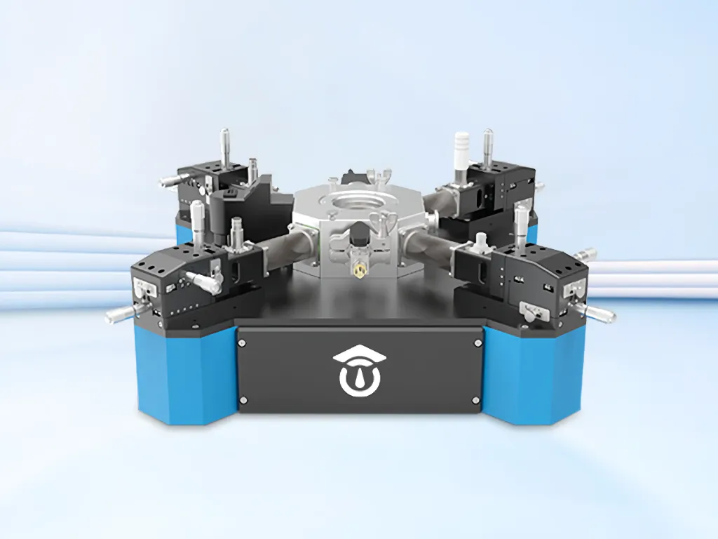
Executing temperature coefficient of capacitance (TCC) tests down to sub-zero regimes (-55°C to -160°C) presents severe condensation hazards in ambient air, where frost accumulation bridges external terminations and causes false leakage failures. The MatMeas CPS-7000 high-low temperature dielectric vacuum probe station overcomes these environmental artifacts by enclosing the testing stage within a high-vacuum chamber (< 10^-2 Pa). By chilling via liquid nitrogen and heating up to 450°C, the system enables frost-free, artifact-free TCC and IR evaluations across automotive and aerospace temperature profiles.
Furthermore, because modern 0201 and 01005 MLCC micro-terminations measure less than 200 micrometers across, ambient building vibrations can dislodge contact probes during continuous thermal sweeps. The MatMeas CPS-7000 incorporates an integrated pneumatic vibration-isolation architecture, ensuring stable, sub-micron probe tip engagement throughout thermal cycling and preventing mechanical contact bounce from introducing false data jumps.
FAQ
Q: Why does capacitance drop dramatically when a DC bias is applied to an X7R capacitor, but not to a C0G capacitor?
A: C0G capacitors utilize Class I paraelectric ceramics (like CaZrO3) that do not possess switchable ferroelectric domains; their polarization is linear with electric field, resulting in 0% DC bias degradation. Conversely, X7R capacitors utilize Class II ferroelectric barium titanate (BaTiO3). When an external DC voltage is applied, the switchable ferroelectric domains align with the field and lock into place. This eliminates the extrinsic domain wall motion that provides the majority of the material's dielectric constant, reducing capacitance by up to 60% to 80% at rated voltage.
Q: What is the physical role of oxygen vacancies in MLCC HALT lifetime failure?
A: During high-temperature sintering in reducing atmospheres (necessary to prevent base-metal nickel electrodes from oxidizing), oxygen vacancies (V_O^••) are inherently generated in the BaTiO3 lattice. Under accelerated electrical stress (HALT), these positively charged vacancies migrate toward the cathode. Over hundreds of hours, they pile up at the dielectric-metal boundary, lowering the interfacial Schottky barrier height. This permits massive electron injection into the conduction band, causing leakage current to escalate exponentially until catastrophic thermal-electric avalanche breakdown occurs.
Q: How does vacuum-environment probing prevent false failures during cryogenic MLCC screening?
A: Standard sub-zero testing (-55°C) in ambient air causes atmospheric moisture to condense and freeze across the tiny termination gap of the capacitor. During temperature transitions near 0°C, melting water forms an ultra-conductive surface path, causing insulation resistance to plummet and registering as a false dielectric breakdown. Vacuum probe stations like the MatMeas CPS-7000 evacuate atmospheric air before cooling, ensuring a 100% dry, frost-free testing environment that captures pure internal dielectric transport.
Request High-Precision Testing Solutions
Get expert guidance and customized instruments for your functional materials project.