Piezoelectric Ceramics Relative Permittivity Testing
Technical News
Piezoelectric ceramics—ranging from classic lead zirconate titanate (PZT) compositions to advanced lead-free potassium sodium niobate (KNN) and relaxor ferroelectric single crystals—form the core functional backbone of ultrasound imaging transducers, precision nanopositioning actuators, sonar arrays, and high-frequency acoustic resonators. In research and industrial quality assurance, piezoelectric charge coefficients such as d33 frequently dominate performance discussions. However, the relative permittivity (also referred to as the dielectric constant, εr) serves as an equally fundamental constitutive parameter that dictates device electrical impedance, internal capacitive energy density, electrical matching to driver circuits, and operational bandwidth.
Accurately measuring the relative permittivity of piezoelectric materials requires rigorous separation of intrinsic dielectric polarization from extrinsic electromechanical resonance, boundary clamping constraints, and environmental thermal artifacts. Because piezoelectric ceramics inherently couple mechanical strain with electrical displacement, their measured permittivity shifts drastically between low-frequency mechanically unconstrained conditions and high-frequency clamped regimes. Testing across wide temperature and frequency spectra under standardized IEEE and IEC protocols provides the foundational data needed to engineer reliable electroacoustic systems and prevent in-service thermal depolarization.
Fundamentals of Dielectric Permittivity in Piezoelectric Media
In functional electroceramics, the relative permittivity quantifies the material's ability to polarize and store electrical displacement field energy relative to a vacuum:
ε_r = ε / ε_0
where ε is the absolute permittivity of the ceramic medium and ε_0 is the vacuum permittivity constant (approximately 8.854 * 10^-12 F/m). Under alternating excitation fields, dielectric displacement exhibits a finite phase lag relative to the applied electric field, resulting from domain wall friction, dipolar orientation latency, and internal defect relaxation. The complex permittivity is formulated as:
ε* = ε' - i * ε''
tanδ = ε'' / ε'
Here, ε' represents the real relative permittivity (polarization storage), ε'' denotes the dielectric loss factor (dissipative conduction and phase lag), and tanδ is the dielectric dissipation factor. In power ultrasonic transducers and resonant actuators, excessive tanδ causes severe internal ohmic and dielectric heating, which can drive the ceramic past its phase transition threshold and trigger catastrophic depolarization.
Because piezoelectric ceramics possess non-centrosymmetric crystalline unit cells, an applied electric field induces mechanical strain, while mechanical stress induces surface charge. Consequently, the measured capacitance and extracted relative permittivity depend fundamentally on the mechanical boundary condition imposed during testing.
Mechanically Free vs. Mechanically Clamped Permittivity
Standardized metrology conforming to IEEE Std 176 and IEC 60483 recognizes two distinct dielectric states in piezoelectric resonators:
- Mechanically Free Permittivity (ε33_T): Measured at frequencies far below the lowest fundamental mechanical resonance of the specimen (typically at 1 kHz). In this sub-resonant regime, the ceramic expands and contracts freely in phase with the applied alternating field. The dielectric displacement incorporates both direct electrical polarization and secondary piezoelectric strain-induced polarization.
- Mechanically Clamped Permittivity (ε33_S): Measured at frequencies well above fundamental resonant and anti-resonant modes (often in the megahertz domain), or under rigid external mechanical constraint. In this regime, the physical inertia of the ceramic mass prevents dimensional deformation. The mechanical strain is effectively zero (
S = 0), isolating pure lattice and electronic polarization.
The mathematical relationship connecting the free relative permittivity ε33_T and the clamped relative permittivity ε33_S is governed by the longitudinal electromechanical coupling coefficient k33:
ε33_S = ε33_T * (1 - k33^2)
Similarly, for thin circular ceramic disks operating in the radial planar mode, the relationship incorporates the planar coupling factor kp:
ε33_p = ε33_T * (1 - kp^2)
For high-coupling ferroelectric ceramics such as soft PZT-5H or single-crystal PMN-PT where k33 can exceed 0.75 to 0.90, the clamped permittivity can be less than half of the free low-frequency value. Conflating these two parameters leads to severe impedance mismatches when designing driver circuitry, matching networks, and power amplifiers.
| Metrological Parameter | Mechanically Free State (ε33_T) | Mechanically Clamped State (ε33_S) |
|---|---|---|
| Testing Frequency Domain | Low frequency: 100 Hz to 10 kHz (typically 1 kHz) | High frequency: well above anti-resonance (MHz range) |
| Boundary Condition | Zero mechanical stress (T = 0); unconstrained motion | Zero mechanical strain (S = 0); inertial clamping |
| Polarization Components | Intrinsic dipolar + extrinsic piezoelectric strain | Pure intrinsic dipolar + lattice electronic displacement |
| Governing Standard | ASTM D150, IEEE Std 176, IEC 60483 | IEEE Std 176, IEC 60483 |
| Capacitive Magnitude | Maximum value; includes electromechanical feedback | Reduced value; suppressed by factor of (1 - k^2) |
| Primary Engineering Application | Sensor circuit matching, low-frequency filter design | Ultrasonic delay lines, medical imaging transducer arrays |
Benchmark Dielectric Properties Across Key Piezoelectric Systems
Selecting and validating piezoelectric formulations requires comparing free permittivity, dielectric loss, and thermal transition boundaries across both lead-based and lead-free material classes.
| Piezoelectric Material Class | Chemical Composition / Type | Free Permittivity (ε33_T / ε_0 @ 1 kHz) | Clamped Permittivity (ε33_S / ε_0) | Dielectric Loss (tanδ @ 1 kHz) | Longitudinal Coupling (k33) | Curie Temperature Tc (°C) |
|---|---|---|---|---|---|---|
| Hard PZT (PZT-4) | Modified Pb(Zr,Ti)O3 (Acceptor Fe/Mn doped) | 1,300 - 1,450 | 680 - 780 | ≤ 0.004 | 0.70 | 328 |
| High-Power PZT (PZT-8) | Acceptor-doped PZT for high mechanical drive | 1,000 - 1,150 | 510 - 600 | ≤ 0.003 | 0.68 | 300 |
| Soft PZT (PZT-5A) | Donor-doped (Nb/La) high-sensitivity sensor grade | 1,700 - 1,900 | 830 - 950 | ≤ 0.018 | 0.71 | 365 |
| High-Permittivity PZT (PZT-5H) | High-capacitance actuator grade | 3,400 - 3,800 | 1,450 - 1,700 | ≤ 0.022 | 0.75 | 195 |
| Relaxor Crystal (PMN-PT) | 0.72Pb(Mg1/3Nb2/3)O3 - 0.28PbTiO3 single crystal | 5,000 - 6,500 | 950 - 1,300 | ≤ 0.008 | 0.92 | 150 |
| Lead-Free KNN | (K,Na)NbO3 modified perovskite ceramic | 1,100 - 1,500 | 650 - 900 | ≤ 0.025 | 0.65 | 410 |
| Lead-Free BNT-BT | (Bi1/2Na1/2)TiO3 - BaTiO3 solid solution | 750 - 1,050 | 450 - 650 | ≤ 0.035 | 0.58 | 280 |
As detailed in the benchmark data, high-permittivity actuator ceramics like PZT-5H provide large electrical capacitance per unit volume, enabling lower drive voltages for a given charge transfer. However, their lower Curie temperatures (under 200°C) and elevated dissipation factors make them unsuitable for continuous high-intensity acoustic transmission, where hard PZT-4 and PZT-8 ceramics are strictly required.
Temperature-Dependent Permittivity and Phase Transitions
Relative permittivity is inherently dynamic across temperature. In ferroelectric ceramics, thermal excitation alters domain wall mobility and drives polymorphic structural transformations. Evaluating permittivity as a continuous function of temperature reveals critical phase boundaries:
- Rhombohedral-Tetragonal Phase Boundary: In modified compositions, shifting across the morphotropic phase boundary (MPB) with changing temperature causes distinct steps or local peaks in permittivity.
- Curie Temperature (Tc): As temperature rises toward the Curie point, the spontaneous polarization decays and thermal disorder intensifies, causing the relative permittivity to surge to a sharp peak. Above Tc, the material transitions to a centrosymmetric paraelectric phase, losing all piezoelectric activity. In this paraelectric regime, the permittivity obeys the classic Curie-Weiss relation:
ε_r = C / (T - T_0)
where C is the Curie-Weiss constant, T is temperature in Kelvin, and T_0 is the Curie-Weiss temperature.
The temperature coefficient of capacitance (TCC) measures the fractional rate of permittivity change over a defined operational window:
TCC = [ (ε_r(T) - ε_r(T_ref)) / ε_r(T_ref) ] * [ 1 / (T - T_ref) ]
Sensors deployed in automotive drivetrains, downhole drilling, or aerospace turbines require minimized TCC to ensure signal linearity and avoid false readings.
Precision Metrology and Artifact Suppression
Executing reliable permittivity measurements across wide temperature ranges (-160°C to 450°C) presents severe experimental hurdles, particularly around cryogenic condensation and thermal stabilization.
In standard open-atmosphere cryostats cooled with liquid nitrogen, ambient water vapor condenses and freezes onto the specimen surface. During subsequent heating sweeps, melting ice forms an ultra-conductive aqueous film across the electrode gap near 0°C. This introduces massive, deceptive "water relaxation peaks" in dielectric loss and artificial spikes in apparent permittivity that can completely obscure true material phase transitions.
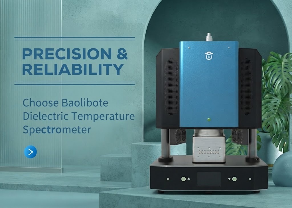
Modern characterization protocols eliminate these measurement artifacts by integrating parallel-plate test fixtures inside an evacuable, high-vacuum test chamber, such as the MatMeas DMS-2000 high-low temperature dielectric spectrometer. By maintaining an environmental vacuum below 10^-1 Pa prior to thermal cycling, surface moisture adsorption is completely prevented, delivering pristine, frost-free dielectric spectra from cryogenic depths to well above the Curie transition.
Additionally, standard liquid nitrogen immersion baths induce violent fluid boiling, which transmits severe mechanical vibrations to sensitive spring-loaded contact electrodes and introduces erratic temperature steps. The MatMeas DMS-2000 overcomes this limitation through its dedicated LNP-95 liquid nitrogen controlled vaporization and injection system. By delivering micro-metered, vaporized nitrogen gas rather than boiling liquid, the system maintains ultra-smooth, continuous temperature ramps with thermal stability within ±0.5°C, ensuring high data reproducibility in compliance with ASTM D150.
Engineering Best Practices for Specimen Preparation
To ensure high data fidelity when testing relative permittivity, laboratory technicians must adhere to strict geometric and contact guidelines:
- Electrode Planarity and Parallelism: Test specimens should be fabricated as thin circular disks with thickness-to-diameter ratios between 1:10 and 1:20. Lapping both faces to parallel tolerances within ±5 micrometers prevents non-uniform electric field distribution.
- Electrode Deposition: Fired-on silver paste, sputter-coated gold (Au), or platinum (Pt) thin films must cover the entire active face while preventing edge wrap-around that could create edge-tracking breakdown paths.
- Fringing Field Correction: For unshielded two-terminal electrode setups, edge capacitance corrections must be applied per ASTM D150:
C_edge = (0.0019 * ε_r - 0.00252 * ln(t) + 0.0068) * P
where t is thickness in centimeters and P is perimeter in centimeters. Utilizing a guarded three-terminal electrode configuration eliminates the need for empirical edge corrections by shunting fringing field lines directly to system ground.
FAQ
Q: How does the Curie temperature determine the maximum continuous operating limit of a piezoelectric ceramic?
A: The Curie temperature (Tc) marks the physical phase transition from the non-centrosymmetric ferroelectric state to a centrosymmetric paraelectric state, where piezoelectricity vanishes entirely. However, practical engineering safety guidelines dictate that piezoelectric components must not operate above 50% to 60% of their Curie temperature. Sustained thermal exposure above this threshold, especially under mechanical stress or electric fields, initiates gradual domain realignment and permanent thermal depolarization long before Tc is reached.
Q: Why does relative permittivity drop substantially at frequencies above mechanical resonance?
A: At frequencies below resonance, the piezoelectric ceramic is mechanically free, allowing both internal dipolar polarization and physical dimensional strains to contribute to the dielectric displacement. Above fundamental acoustic resonances, the physical inertia of the specimen prevents mechanical deformation in phase with the oscillating excitation field. The ceramic becomes inertially clamped (S = 0), eliminating the piezoelectric strain contribution and reducing the measured permittivity by a factor of (1 - k^2).
Q: What is the primary cause of anomalous dielectric loss peaks near 0°C during temperature sweeps?
A: Anomalous dielectric loss peaks near 0°C are almost universally caused by atmospheric moisture condensing and freezing onto the ceramic surface during cryogenic cooling. As the sample warms past 0°C, the phase change to liquid water introduces a high-conductivity surface bypass path that registers as an artificial relaxation peak. Operating within a sealed, vacuum-evacuated test chamber, as implemented in the MatMeas DMS-2000, completely eliminates atmospheric water vapor and ensures clean dielectric spectra.
Request High-Precision Testing Solutions
Get expert guidance and customized instruments for your functional materials project.