Piezoelectric d33-F (Dynamic Force) Testing: Accurately Characterizing Dynamic Performance
Technical News
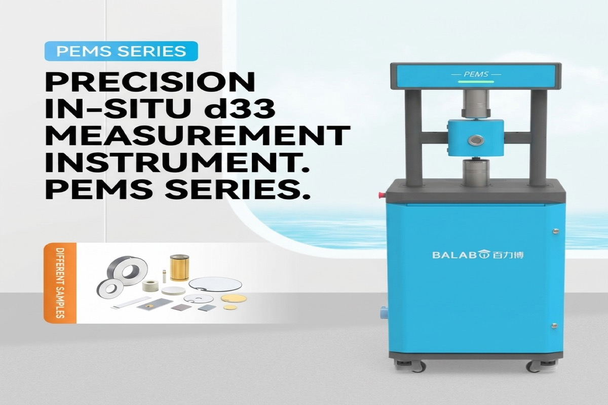
Piezoelectric materials function as the core electromechanical transduction medium across precision industrial actuators, ultrasonic medical transducers, naval sonar arrays, vibration energy harvesters, and high-g acceleration sensors. Among the comprehensive matrix of electro-elastic tensors defining these anisotropic crystalline and polycrystalline ceramics, the longitudinal piezoelectric charge coefficient d33 represents the primary figure of merit. It quantifies the electric displacement or dielectric surface polarization charge density generated along the polar 3-axis per unit of uniaxial mechanical stress applied collinearly along that same direction.
Under classical linear piezoelectric constitutive theory governed by IEEE Std 176 and IEC 60483, the direct and converse piezoelectric coupling interactions are described by the coupled tensor relations:
D3 = d33 * T3 + epsilon33_T * E3
S3 = s33_E * T3 + d33 * E3
Here, D3 represents the longitudinal electric displacement (C/m2), T3 denotes the applied mechanical uniaxial stress (N/m2), epsilon33_T is the dielectric permittivity measured under unconstrained mechanical boundary conditions (stress T = 0), E3 is the internal electric field (V/m), S3 is the mechanical strain along the polar axis, and s33_E denotes the elastic compliance measured under short-circuit electrical conditions (electric field E = 0).
In conventional quality control protocols, the longitudinal piezoelectric coefficient is routinely quantified using standard Berlincourt-type quasi-static d33 meters. However, relying solely on room-temperature quasi-static measurements introduces severe blind spots for mission-critical transducer engineering. Operating a transducer in an aerospace jet engine monitor, an ultrasonic surgical scalpel, or an automotive knock sensor subjects the active ceramic element to continuous alternating stresses, substantial mechanical preloads (clamping pressures ranging from 10 MPa to over 80 MPa), elevated thermal gradients, and variable mechanical excitation frequencies. Under these harsh operating realities, the material exhibits pronounced non-linear ferroelastic domain switching, mechanical internal friction, phase lag between stress and strain, and significant thermal-pyroelectric interference. Consequently, dynamic force d33 testing (d33-F testing) across swept frequencies and variable alternating loads has emerged as an indispensable metrological paradigm.
Why Quasi-Static Berlincourt Metrology Fails in Dynamic Operating Regimes
Standard quasi-static d33 meters, originally commercialized based on the Berlincourt method, operate by subjecting a pre-polarized piezoelectric sample to an electromagnetic shaker oscillating at an arbitrary low fixed frequency—typically between 110 Hz and 115 Hz—with a diminutive alternating force amplitude (delta_F roughly 0.25 N) superimposed upon a manual static clamping preload (typically 1 N to 2 N). The charge output generated across the sample electrodes is compared via an analog rectification or peak-detection circuit against a built-in standard quartz or hard PZT reference element.
While fast and practical for basic sorting of unmounted ceramic discs, this quasi-static technique exhibits three structural limitations that invalidate its data for high-power or wideband sensor engineering:
- Insensitivity to Mechanical Dissipation and Phase Lag: The standard Berlincourt method treats the piezoelectric coefficient strictly as a pure, real-valued scalar quantity. In reality, all ferroelectric ceramics possess internal mechanical and electrical damping caused by the sluggish motion of 90-degree and 180-degree domain walls. Under cyclic dynamic stress, the induced electric charge lags behind the applied mechanical force waveform by a finite loss angle theta. Neglecting this phase lag prevents engineers from predicting internal self-heating and acoustic dissipation inside high-duty transducers.
- Inability to Characterize Rayleigh Non-Linearities: When a piezoelectric ceramic is driven under realistic sensor loads or acoustic shock conditions (where alternating forces exceed several tens of Newtons), the electromechanical response ceases to be linear. Domain wall pinning centers (such as oxygen vacancies, acceptor dopants, and grain boundary dislocations) are overcome by the cyclic stress, introducing irreversible domain displacements. A single-point test at 0.25 N dynamic force cannot detect the onset of non-linear hysteresis.
- Severe Thermal Drift and Pyroelectric Corruption: Real-world transducers frequently operate between -55 C and +250 C (and up to 600 C for high-temperature bismuth titanates). When heating a sample inside a thermal chamber, temperature fluctuations generate massive pyroelectric displacement currents (I_pyro = p * A * dT/dt). Standard quasi-static meters cannot separate this continuous DC/low-frequency pyroelectric charge baseline from the genuine mechanical piezoelectric signal, yielding false d33 values with errors frequently exceeding 40% to 100%.
To illustrate the architectural and metrological divide between conventional inspection tools and dynamic characterization platforms, the comparative engineering parameters are summarized in the table below.
| Metrological Parameter | Standard Quasi-Static Berlincourt Meter | Dynamic Force (d33-F) Frequency-Sweep Testing Platform |
|---|---|---|
| Excitation Frequency | Fixed single frequency (110 Hz to 115 Hz) | Continuously programmable frequency sweep (30 Hz to 300 Hz and resonance bands) |
| Dynamic Force Amplitude (delta_F) | Fixed minimal amplitude (~0.20 N to 0.25 N) | Variable dynamic excitation (0.05 N to 10.0 N RMS, closed-loop electrodynamic drive) |
| Static Preload Control | Manual spring or coarse screw clamp (uncalibrated, 1 N to 5 N) | Servo-controlled motorized closed-loop preload (0.1 N to 50.0 N continuous monitoring) |
| Complex Parameter Extraction | Real scalar d33 only (no phase angle information) | Complex piezoelectric tensor: real d33', imaginary d33'', and mechanical loss angle theta |
| Non-Linear Dynamics Mapping | None; assumes strict linear constitutive response | Maps Rayleigh non-linear coefficient (alpha_F) and threshold stress across dynamic force sweeps |
| Thermal Range Capability | Strictly ambient room temperature (~20 C to 25 C) | In-situ environmental control (-160 C cryogenic up to +600 C extreme high temperature) |
| Thermal Current Decoupling | Zero decoupling; thermal drift causes massive signal saturation | Lock-in phase-sensitive amplification; orthogonal decoupling of pyroelectric background |
| Primary Fixture Compliance Error | High; bending modes in handheld clamps create shear false signals | Ultra-rigid axial guide stages with spherical self-aligning contact tips to eliminate bending |
Complex Piezoelectric Constitutive Equations and Phase Lag Dynamics
To rigorously capture the dynamic electromechanical behavior under cyclic harmonic stress, the longitudinal piezoelectric coefficient must be formulated as a complex mathematical quantity. When a sinusoidal mechanical force F(t) is exerted along the 3-axis of a poled piezoelectric specimen:
F(t) = F_static + F_dynamic * sin(omega * t)
The resulting electrical charge response Q(t) monitored across the short-circuited electrodes oscillates at the identical angular frequency omega = 2 * pi * f, but exhibits a temporal phase shift theta:
Q(t) = Q_static + Q_dynamic * sin(omega * t - theta)
Expressing the dynamic stress and resulting dielectric polarization in harmonic complex phasor notation yields the complex longitudinal piezoelectric coefficient d33*:
d33* = d33' - i * d33'' = |d33| * exp(-i * theta)
In this constitutive representation:
- Real Piezoelectric Component (d33'): Represents the elastic, reversible polarization charge in instantaneous phase alignment with the cyclic mechanical force. This term governs the recoverable electromechanical energy conversion.
- Imaginary Piezoelectric Component (d33''): Represents the dissipative loss component resulting from mechanical damping, dielectric relaxation, and irreversible microscopic domain wall pinning-unpinning friction.
- Electromechanical Loss Tangent (tan theta): Directly quantifies the phase lag and internal heat generation rate within the transducer ceramic:
tan(theta) = d33'' / d33'
|d33| = sqrt((d33')^2 + (d33'')^2)
When high-power transducers operate near mechanical resonance or under heavy acoustic loads, a large imaginary coefficient d33'' leads to thermal runaway. As the internal temperature climbs, depoling occurs, causing complete operational failure. Dynamic d33-F testing provides the exact value of d33'' and tan theta across both frequency and load spectra, allowing acoustic designers to balance coupling efficiency against thermal dissipation.
Non-Linear Stress Regimes and Rayleigh Domain Wall Mechanics
Under small mechanical forces (delta_F < 0.5 N), the motion of ferroelectric domain walls remains strictly reversible within local shallow potential wells created by crystalline point defects. Within this sub-threshold regime, d33 remains essentially independent of the applied dynamic force amplitude.
However, as the alternating dynamic force amplitude increases into the range typical of industrial actuators (several Newtons to tens of Newtons), domain walls acquire sufficient mechanical energy to overcome deep pinning barriers. This non-linear behavior is governed by the electromechanical Rayleigh law:
d33(F_dynamic) = d33_init + alpha_F * F_dynamic
Where:
- d33_init: The intrinsic, low-field reversible piezoelectric coefficient attributable to pure crystal lattice distortion and reversible domain boundary oscillations.
- alpha_F: The Rayleigh non-linear force coefficient, which directly measures the density and mobility of irreversible domain wall displacements per unit of applied cyclic force.
Evaluating alpha_F via automated dynamic force sweeps reveals critical metallurgical differences between "hard" and "soft" piezoelectric formulations. For instance, in acceptor-doped hard ceramics (such as Fe-doped or Mn-doped PZT-8), defect dipoles align to create powerful internal stabilizing bias fields that clamp domain walls, yielding an exceptionally small alpha_F and maintaining linear, low-loss response even under 10 N dynamic loads. Conversely, donor-doped soft ceramics (such as Nb-doped or La-doped PZT-5H) exhibit massive alpha_F values, resulting in severe non-linear harmonic distortion, amplitude-dependent calibration drift, and rapid temperature escalation when driven dynamically.
The following benchmark table presents typical dynamic piezoelectric properties, non-linear thresholds, and thermal operating envelopes across standard functional materials classes.
| Piezoelectric Material Category | Typical Composition Base | Quasi-Static d33 (pC/N) | Dynamic d33' at 100 Hz (pC/N) | Dynamic Loss Factor (tan theta at 100 Hz) | Rayleigh Coeff. alpha_F (pC/N^2) | Maximum Depoling Temp (T_max) | Typical Transducer Application Envelope |
|---|---|---|---|---|---|---|---|
| Hard PZT (Navy Type III) | Pb(Zr_0.54 Ti_0.46)O3 + Mn/Fe | 220 to 250 | 215 to 245 | < 0.005 (0.5%) | 0.8 to 1.5 | 320 C | High-power ultrasonic cleaning, naval sonar emitters, deep-hole acoustic drills |
| Soft PZT (Navy Type II) | Pb(Zr_0.52 Ti_0.48)O3 + Nb/La | 550 to 650 | 520 to 610 | 0.020 to 0.035 (2.0% - 3.5%) | 8.5 to 14.0 | 180 C | Medical ultrasound diagnostic probes, precision piezo nanopositioning stages |
| Lead-Free Perovskite | (K_0.5 Na_0.5)NbO3 (KNN-based) | 280 to 420 | 260 to 390 | 0.015 to 0.028 (1.5% - 2.8%) | 4.0 to 7.2 | 220 C | Bio-compatible implantable sensors, eco-compliant consumer acoustic transducers |
| Ultra-High Temp Bismuth Layer | Bi4Ti3O12 / CaBi4Ti4O15 | 18 to 25 | 18 to 24 | < 0.003 (0.3%) | < 0.2 | 600 C | Nuclear reactor core pressure monitoring, jet turbine acoustic combustion analysis |
| Relaxor Single Crystal | Pb(Mg_1/3 Nb_2/3)O3-PbTiO3 (PMN-PT) | 1800 to 2500 | 1650 to 2300 | 0.010 to 0.020 (1.0% - 2.0%) | 18.0 to 32.0 | 130 C | High-end intravascular ultrasound (IVUS), military active phased-array sonars |
| Piezoelectric Fluoropolymer | PVDF / P(VDF-TrFE) Film | -28 to -34 | -24 to -30 | 0.035 to 0.060 (3.5% - 6.0%) | 1.2 to 2.8 | 90 C | Flexible tactile wearable matrices, acoustic pick-ups, structural health skin monitors |
Hardware Architecture for In-Situ Dynamic Force Characterization
Executing rigorous dynamic d33 testing across varying temperatures, preloads, and frequencies requires hardware engineered to isolate mechanical force transfer from electromagnetic cross-talk, stray capacitance, and thermal convection.
The flagship MatMeas PEMS-1000 Piezoelectric Temperature Spectrum Analyzer provides a dedicated architecture for in-situ dynamic force characterization across the 30 Hz to 300 Hz frequency domain. The system combines an electrodynamic voice-coil vibrator stage with an independent high-precision motorized static preload actuator. The specimen is supported within a specialized low-expansion test chamber capable of executing continuous temperature profiles from -160 C up to +600 C.
During dynamic sweeps, the total instantaneous current I_total(t) entering the test electronics contains three distinct physical contributions:
I_total(t) = d33 * (dF/dt) + p * A * (dT/dt) + (V_bias / R_insulation)
Where:
- d33 * (dF/dt): The desired dynamic piezoelectric displacement current, oscillating at frequency omega.
- p * A * (dT/dt): The background pyroelectric current generated by the thermal chamber's heating rate dT/dt across sample area A with pyroelectric coefficient p.
- V_bias / R_insulation: Parasitic leakage current passing through the finite bulk insulation resistance R_insulation.
To extract pristine d33 data without thermal distortion, the PEMS-1000 routes the sensor output through a digital dual-phase lock-in amplifier referenced directly to the dynamic force load cell drive signal. Because the pyroelectric current is either quasi-DC (driven by a linear 2 C/min thermal ramp) or phase-shifted by 90 degrees relative to mechanical acceleration, the lock-in multiplier mathematically rejects the pyroelectric current and broad-spectrum Johnson noise, resolving ultra-weak charges down to 0.01 pC with total signal-to-noise ratios exceeding 80 dB.
For applications requiring ultra-high-resolution baseline calibration or evaluation of thin, fragile sensor plates where heavy dynamic loads risk mechanical micro-cracking, the MatMeas PEAI-1000 High-Precision Piezoelectric Analyzer serves as an ideal complementary metrology station. The PEAI-1000 operates with finely resolved static clamping forces (calibrated from 1 N to 10 N in 0.1 N increments) and ultra-stable alternating test loads (0.05 N to 0.5 N). Its low-noise virtual-ground electrometer architecture provides baseline accuracy within +/-2%, guaranteeing pristine data on delicate single crystals, porous ceramics, and micro-electromechanical systems (MEMS) elements prior to destructive high-load cycling.
Standardized Step-by-Step SOP for Dynamic d33-F Characterization
To achieve reproducible test results in compliance with IEEE Std 176 and internal aerospace quality assurance protocols, test engineers should follow this structured testing SOP:
Step 1: Geometric Preparation and Electrode Sintering
- Verify that sample faces are flat, parallel, and free of edge chipping. Parallelism between top and bottom faces must be maintained within +/-0.01 mm to prevent bending stresses during axial clamping.
- Polish opposing surfaces and apply uniform fired-on silver paste or magnetron-sputtered gold/platinum electrodes with a wrap-around perimeter margin of at least 0.5 mm to prevent edge breakdown during subsequent high-voltage poling.
- Clean the specimen in an ultrasonic bath using electronic-grade isopropanol and bake at 120 C for 30 minutes to eliminate all residual surface moisture.
Step 2: Mechanical Alignment and Preload Calibration
- Mount the sample centrally on the lower anvil of the dynamic testing platform. Ensure that the hemispherical top contact probe aligns collinearly with the geometric center of the electrode to eliminate torsional and shear moments.
- Engage the motorized servo-stage to apply the specified static baseline clamping preload (typically 5.0 N for standard bulk ceramic discs).
- Verify that the static force sensor reading has settled with less than 0.05 N drift over a 60-second window.
Step 3: Dynamic Force Amplitude and Frequency Sweep
- Program the electrodynamic actuator to superimpose a sinusoidal dynamic force delta_F (e.g., starting at 0.25 N RMS and stepping progressively to 0.5 N, 1.0 N, 2.5 N, and 5.0 N).
- For each dynamic force setpoint, perform a logarithmic frequency sweep between 30 Hz and 300 Hz. Avoid testing near sample acoustic resonance frequencies, which produce inertial mass loading artifacts.
- Record the real charge component (d33'), imaginary loss component (d33''), and mechanical dissipation angle (theta) at each frequency and force increment.
Step 4: Temperature-Dependent Dynamic Profiling (Optional)
- If characterizing temperature limits, establish a controlled thermal ramp rate (recommended: 1.0 C/min to 2.0 C/min) inside the environmental furnace.
- Maintain active lock-in phase-tracking to continuously strip away the pyroelectric background current p * A * (dT/dt).
- Log data until the Curie transition or thermal depoling threshold is reached, identified by a sudden collapse of d33' toward zero accompanied by a spike in tan theta.
Frequently Asked Questions (FAQ)
Why do standard Berlincourt meters fail to predict real-world piezoelectric transducer performance?
Standard Berlincourt meters operate exclusively under quasi-static conditions at room temperature using an uncalibrated low dynamic force (~0.25 N) at a single frequency (~110 Hz). Real-world transducers operate under multi-megapascal mechanical preloads, broad frequency spectra, elevated temperatures, and cyclic fatigue stresses. These working conditions trigger non-linear domain wall switching, phase lag, and thermal depoling that static meters cannot detect.
What physical mechanism causes the dynamic piezoelectric coefficient to exhibit a phase lag angle theta?
The phase lag theta arises from electromechanical internal friction and time-dependent domain wall motion. As dynamic stress alternates, the displacement of 90-degree ferroelectric-ferroelastic domain walls encounters resistance from lattice point defects and grain boundary pinning sites. This kinetic lag between applied mechanical stress and domain reorientation manifests as an imaginary piezoelectric component (d33''), dissipating electromechanical energy into heat.
Can the PEMS-1000 perform dynamic d33 measurements at low frequencies like 10 Hz or 20 Hz?
The PEMS-1000 is architecturally optimized for dynamic force direct traceability across a frequency window of 30 Hz to 300 Hz. Testing below 30 Hz increases susceptibility to 1/f mechanical flicker noise, laboratory seismic vibrations, and electrometer charge drift. The 30 Hz to 300 Hz operating band matches the harmonic frequency profile of industrial transducers while delivering superior signal-to-noise ratios.
How does phase-sensitive lock-in detection eliminate pyroelectric interference during temperature sweeps?
During temperature ramping, materials generate a continuous spontaneous polarization change that produces a DC or low-frequency pyroelectric current. The dynamic force excitation operates at a known, high-frequency harmonic carrier (e.g., 110 Hz). By referencing the dual-phase lock-in multiplier to the precise frequency and phase of the force sensor, all non-synchronous current components—including the quasi-DC pyroelectric background and wideband thermal noise—are filtered out mathematically.
Related Instruments & Equipment
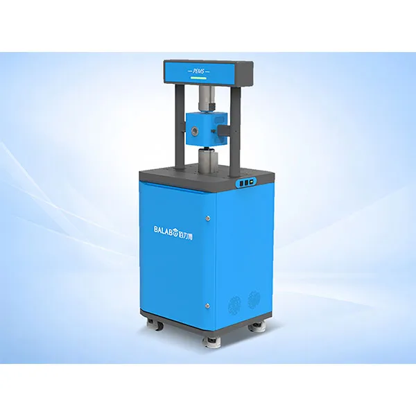
MatMeas High Precision In‑situ d33 Piezoelectric Measurement System – PEMS Analyzer
MatMeas PEMS is a high‑precision in‑situ d33 piezoelectric measurement system for advanced material characterization.
View details →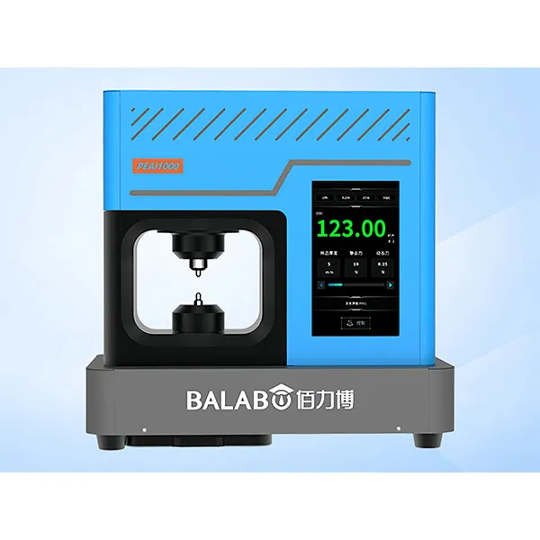
MatMeas PEAI1000 High-Precision Piezoelectric Analyzer
The MatMeas PEAI1000 is a next-generation High-Precision Piezoelectric Analyzer engineered to evaluate the piezoelectric coefficient (d33) of advanced functional materials. Surpassing the limitations of traditional d33 measuring instruments, it employs an advanced dynamic measurement method integrated with cutting-edge lock-in amplification technology. This architecture strictly suppresses environmental noise, significantly improving the signal-to-noise ratio. Capable of applying variable static clamping forces (1~10N) and precise dynamic test forces (0.1~0.5N), it guarantees an ultra-wide measurement range (0 to 2000 pC/N) with an exceptional accuracy of ±2%. It is an essential, highly reliable tool for the research, application, and mass production of piezoelectric blocks, plates, and delicate thin films.
View details →Request High-Precision Testing Solutions
Get expert guidance and customized instruments for your functional materials project.