Piezoelectric Ceramic Volume Resistivity Testing: Purpose and Industrial Applications
Technical News
Piezoelectric ceramics—predominantly lead zirconate titanate (PZT) formulations, modified bismuth layer-structured ferroelectrics, and lead-free alkali niobates—serve as active functional components in high-intensity therapeutic ultrasound (HIFU), sub-nanometer positioning stages, deep-well acoustic logging tools, and automotive common-rail fuel injectors. While piezoelectric charge coefficients (d33) and electromechanical coupling factors (kp) dominate functional device specifications, bulk volume resistivity represents the fundamental parameter governing dielectric integrity and operational survivability.
In both fabrication and operational deployment, piezoelectric ceramics are subjected to intense static and dynamic electric fields. During high-voltage polarization (poling), DC fields exceeding 3 kV/mm to 5 kV/mm are applied at elevated temperatures (100°C to 150°C). During power actuation, high AC fields drive continuous acoustic vibration. If the material's bulk volume resistivity is insufficient, excessive leakage currents generate intense localized Joule heating. Because electrical conductivity escalates exponentially with temperature, this internal heating triggers catastrophic thermal-electric runaway and dielectric puncture. Rigorous volume resistivity testing conforming to ASTM D257, ASTM D1829, and IEC 60093 standards across room temperature to 800°C and beyond is mandatory to screen out latent microstructural flaws and establish safe operating voltage envelopes.
Conduction Mechanisms and Kroger-Vink Point Defect Kinetics
Under ambient conditions, pristine piezoelectric ceramics exhibit near-ideal electrical isolation, with room-temperature volume resistivities exceeding 10^12 Ω·cm to 10^14 Ω·cm. However, electrical resistance decays exponentially as temperature rises, governed by thermally activated carrier hopping described by Arrhenius kinetics:
σ(T) = 1 / ρ_v(T) = σ_0 * exp[ -E_a / ( k_B * T ) ]
where σ(T) is electrical conductivity, ρ_v is volume resistivity, σ_0 is the conductivity pre-exponential factor, E_a is the conduction activation energy, k_B is the Boltzmann constant (8.617 * 10^-5 eV/K), and T is absolute temperature in Kelvin.
In perovskite PZT electroceramics, high-temperature electrical conduction is dominated by the migration of point defects created during high-temperature sintering. Because lead oxide (PbO) possesses high vapor pressure, volatilization of Pb during firing at >1200°C induces lead and oxygen vacancies in accordance with Kroger-Vink defect notation:
Pb_Pb^x + O_O^x <==> PbO(g) + V_Pb'' + V_O^••
where V_Pb'' represents a doubly negatively charged lead vacancy, and V_O^•• represents a doubly positively charged oxygen vacancy.
Under elevated temperatures (>200°C) and strong electric fields, positively charged oxygen vacancies V_O^•• mobilize, hopping across adjacent octahedral oxygen sites with activation energies typically ranging from 0.85 eV to 1.25 eV. At higher temperatures (>500°C), electron hole conduction (h^•) and intrinsic band-to-band transitions activate, yielding activation energies exceeding 1.8 eV to 2.2 eV.
This defect migration induces severe operational risks:
- Electrode Polarization & Space-Charge Piling: Mobile oxygen vacancies accumulate beneath cathode interfaces, forming localized space-charge fields that trigger electron injection and premature electrical breakdown.
- Thermal-Electric Runaway: The internal volumetric Joule dissipation density is given by:
P_joule = E^2 * σ(T) = E^2 * σ_0 * exp[ -E_a / ( k_B * T ) ]
When internal Joule heat generation outpaces the ceramic's thermal dissipation capability, temperature rises uncontrollably, driving electrical resistance down until catastrophic dielectric thermal breakdown occurs.
| Piezoelectric Ceramic Formulation | Compositional / Dopant Type | 25°C Volume Resistivity (Ω·cm) | 200°C Volume Resistivity (Ω·cm) | 400°C Volume Resistivity (Ω·cm) | 600°C Volume Resistivity (Ω·cm) | Safe Poling Field Limit @ 120°C (kV/mm) | Conduction Activation Energy Ea (eV) | Curie Temp Tc (°C) |
|---|---|---|---|---|---|---|---|---|
| Soft PZT (PZT-5A) | Donor-doped (Nb5+ / La3+) sensor grade | 1.0 * 10^13 | 5.0 * 10^9 | 8.0 * 10^6 | 2.5 * 10^4 | 2.5 - 3.5 | 0.90 - 1.10 | 365 |
| Hard PZT (PZT-4) | Acceptor-doped (Fe3+ / Mn2+) power grade | 5.0 * 10^13 | 8.0 * 10^10 | 2.0 * 10^7 | 6.0 * 10^4 | 3.5 - 4.5 | 1.15 - 1.35 | 328 |
| High-Power PZT (PZT-8) | High-acceptor doped transducer grade | 1.0 * 10^14 | 2.0 * 10^11 | 5.0 * 10^7 | 1.2 * 10^5 | 4.0 - 5.0 | 1.25 - 1.45 | 300 |
| Bismuth Titanate (BIT) | Aurivillius Bi4Ti3O12 high-temp ceramic | 8.0 * 10^13 | 1.5 * 10^11 | 4.0 * 10^8 | 8.0 * 10^5 | 6.0 - 8.0 | 1.30 - 1.55 | 675 |
| Lithium Niobate (LiNbO3) | Single crystal high-temperature cut | > 1.0 * 10^15 | > 1.0 * 10^13 | 5.0 * 10^9 | 1.5 * 10^7 | 5.0 - 7.0 | 1.40 - 1.65 | 1,150 |
| Lead-Free KNN | (K,Na)NbO3 modified lead-free ceramic | 2.0 * 10^12 | 1.0 * 10^9 | 3.0 * 10^6 | 1.0 * 10^4 | 2.0 - 3.0 | 0.80 - 1.00 | 410 |
Metrological Methodology: ASTM D257 Guarded Three-Ring Architecture
Evaluating volume resistivity in electroceramics requires isolating volumetric current from external surface leakage and fixture shunt leakage. Conforming to ASTM D257, ASTM D1829, and IEC 60093, characterization deploys concentric three-terminal guarded geometry:
High-Voltage DC Excitation (VDC)
═════════════════════════════════════════════════════════════  Unguarded Electrode (d3)
░░░░░░░░░░░░░░░░░░░░░░░░░░░░░░░░░░░░░░░░░░░░░░░░░░░░░░░░░░░░░  Piezoelectric Ceramic (Thickness t)
─────── Guard (d2) ───────     ── Protected (d1) ──     ─────── Guard (d2) ───────
            │                           │                           │
            ▼                           ▼                           ▼
      System Ground              Picoammeter Node             System Ground
   (Surface Leakage Shunted)   (Pure Volume Current)       (Surface Leakage Shunted)
- Protected Center Electrode (d1): Circular contact on the top face that captures pure volumetric current traversing the ceramic thickness.
- Annular Guard Ring (g, d2): Concentric ring surrounding the protected electrode with radial gap
g. Maintained at an identical potential to the measurement electrode, the guard intercepts surface tracking currents and shunts them directly to ground, bypassing the electrometer. - Unguarded Counter Electrode (d3): Continuous bottom electrode connected to the high-voltage DC excitation power supply.
The effective volumetric electrode area A_eff and volume resistivity ρ_v are extracted using standardized geometric relations:
A_eff = ( π / 4 ) * ( d1 + g )^2
ρ_v = R_v * ( A_eff / t )
where R_v is measured volume resistance in ohms and t is ceramic disc thickness in centimeters.
| High-Temperature Testing Hazard | Temperature Window | Underlying Physical Mechanism | Metrological Distortion Impact | Standardized Mitigation Protocol |
|---|---|---|---|---|
| Fixture Insulation Shunt | 500°C to 800°C+ | Ceramic structural insulators become conductive | Masks true sample resistance; artificial ceiling | 99.8% high-purity corundum structural isolators |
| Electrode Air Oxidation | > 300°C in air | Silver or base metal oxidation; interfacial scale | Contact resistance surges; erratic data spikes | Platinum paste / sputtered Au in sealed inert purge |
| Piezoelectric Pyroelectric Drift | Rapid thermal ramps | Spontaneous polarization alters with temperature (dP/dT) | Massive DC current baseline overlaying leakage | Slow ramp rates (≤ 2°C/min); isothermal soak periods |
| Mechanical Cracking under Load | Thermal expansion | Anisotropic thermal expansion causes stress points | Brittle ceramic fractures under rigid clamps | Spring-compliant contact head calibrated to ≤ 0.25 N |
| Transient Polarization Current | Initial voltage step | Geometric charging + slow dipole orientation | Resistance drifts upward over minutes | Standardized 60-second electrification soak time |
Dedicated In-Situ High-Temperature Characterization Platforms
Overcoming high-temperature measurement pitfalls requires specialized test fixtures that preserve multi-teraohm isolation across broad thermal windows.
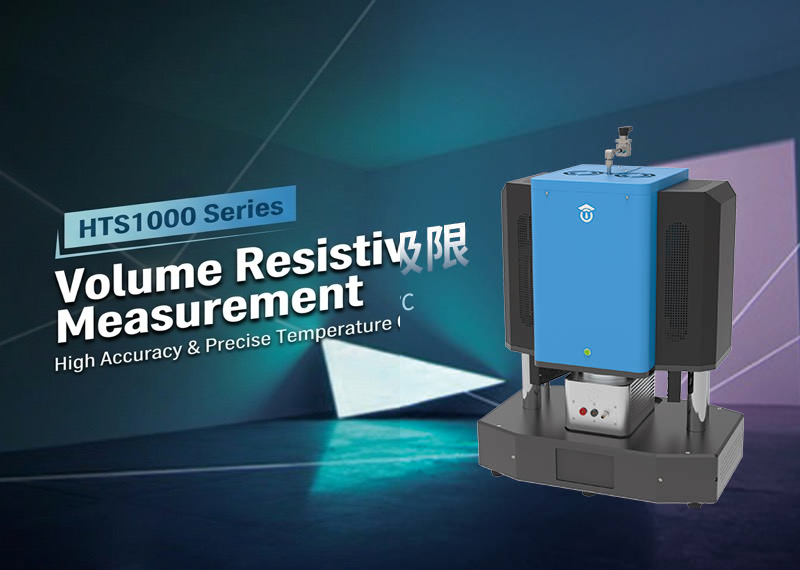
For standard piezoelectric characterization up to 800°C, the MatMeas HTS-1000HR high-temperature resistivity measurement system provides dedicated three-terminal guarded testing. Supporting disc specimens up to 30 mm diameter and 5 mm thickness, the HTS-1000HR spans resistance measurements from 10^3 Ω to 10^15 Ω. To eliminate fixture leakage, structural supports are machined from ultra-high-purity (99.8%) sintered corundum ceramics. Furthermore, to protect delicate, brittle electroceramics from cracking during thermal cycling, the system incorporates a factory-calibrated spring loading head that limits contact force to just 0.25 N. An integrated environmental chamber supports vacuum evacuation down to 10^-1 Pa and inert argon/nitrogen purging, preventing platinum or gold electrode oxidation throughout multi-hour thermal ramps.
For extreme-temperature electroceramics operating in aerospace turbine sensors and deep-well exploration tools—such as bismuth titanate and lithium niobate—testing must extend to extreme thermal limits. The MatMeas RMS-1650 ultra-high-temperature measurement system pushes testing boundaries up to 1600°C. Utilizing heavy-duty molybdenum disilicide (MoSi2) heating elements, multi-layer alumina radiation shielding, and triaxial guarded electrometer circuitry, the RMS-1650 resolves bulk resistivity across sixteen orders of magnitude, providing the empirical foundation needed to validate high-temperature piezoelectric devices against thermal-electric breakdown.
Standardized Specimen Preparation and Testing Best Practices
- Electrode Edge Clearance: Apply circular electrodes centered on both faces, ensuring a minimum unmetallized edge margin of 1.0 mm to 1.5 mm around the perimeter to prevent edge flashover during high-voltage DC excitation.
- Electrification Soak Period: In compliance with ASTM D257, allow a minimum electrification dwell of 60 seconds at each discrete DC voltage step before recording resistance. This allows fast capacitive charging and slow dipolar polarization currents to decay below the steady-state electronic/ionic leakage baseline.
- Thermal Equilibrium: Enforce an isothermal soak time of 5 to 10 minutes at each temperature plateau to ensure uniform thermodynamic equilibrium throughout the ceramic bulk prior to measurement.
FAQ
Q: Why does volume resistivity decrease so dramatically as temperature increases in PZT ceramics?
A: In perovskite PZT ceramics, electrical conduction at elevated temperatures is dominated by the migration of positively charged oxygen vacancies (V_O^••) and thermally activated electronic carriers. At room temperature, these defects are trapped in localized potential wells. As temperature rises, thermal energy provides the activation energy (0.9 eV to 1.3 eV) required for vacancies to hop through the lattice, causing electrical conductivity to increase exponentially in accordance with Arrhenius kinetics and reducing volume resistivity by several orders of magnitude.
Q: What is the primary operational hazard of low volume resistivity during high-voltage poling?
A: During poling, electric fields of 3 kV/mm to 5 kV/mm are applied at temperatures of 100°C to 150°C to align ferroelectric domains. If the ceramic's volume resistivity is too low, the applied field drives large leakage currents through the specimen. The resulting Joule heating (P = V^2 / R) raises the local temperature, which further lowers resistivity in a vicious cycle, triggering catastrophic thermal-electric avalanche breakdown and melting or shattering the ceramic.
Q: Why is a three-terminal guard ring electrode configuration necessary for testing piezoelectric ceramics?
A: Pristine piezoelectric ceramics possess bulk resistance values exceeding 10^12 ohms. Under high-voltage test conditions, parasitic leakage currents traveling across the specimen surface or through air ionization are often orders of magnitude larger than the tiny current passing through the bulk thickness. A guarded three-ring electrode setup diverts surface leakage directly to ground, ensuring that the electrometer captures only intrinsic volume conduction in compliance with ASTM D257.
Related Instruments & Equipment
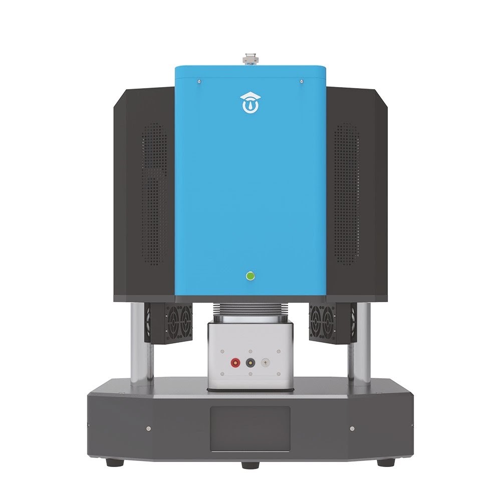
HTS1000HR High Temperature Resistivity Measurement System
The HTS1000HR is an advanced, integrated testing platform specifically engineered to precisely evaluate the electrical conductivity and insulation properties of advanced materials at extreme temperatures up to 800℃. By supporting various atmospheric conditions and offering an ultra-wide resistance measurement range, it serves as an indispensable characterization tool for material research and industrial quality control.
View details →
RMS1650 Ultra-High Temperature Resistivity Measurement System
The RMS1650 Ultra-High Temperature Resistivity Measurement System is engineered for the rigorous electrical characterization of insulating and dielectric materials up to 1600°C. Utilizing a proprietary guarded three-terminal electrode configuration, the system enables in-situ acquisition of resistivity and leakage current kinetics under extreme temperatures, vacuum, and controlled gas atmospheres.
View details →Request High-Precision Testing Solutions
Get expert guidance and customized instruments for your functional materials project.