Volume Resistivity Testing of Piezoelectric Ceramics
Technical News
Volume resistivity (rho_v, expressed in ohm-meters or ohm-centimeters) quantifies a material's intrinsic opposition to electric current flowing through its bulk volume. In the engineering and manufacturing of piezoelectric ceramics—such as lead zirconate titanate (PZT), bismuth titanates (BIT), lead metaniobate, and alkali niobate solid solutions—volume resistivity is not merely a passive insulation metric. It is the decisive operational parameter governing high-voltage poling yield, low-frequency sensor charge retention, actuator energy dissipation, and high-temperature thermal runaway limits.
During high-voltage DC poling (where field strengths between 20 kV/cm and 60 kV/cm are applied at temperatures from 100 C to 200 C to align ferroelectric domains), insufficient volume resistivity triggers high leakage currents. This Joule heating elevates the ceramic temperature, which exponentially lowers resistivity via Arrhenius defect hopping, triggering destructive electrical breakdown.
Furthermore, in dynamic sensor applications (such as seismic geophones, pressure transducers, and acoustic hydrophones), a piezoelectric element functions as a transient charge generator in parallel with its own internal volume resistance. If the volume resistivity is inadequate, generated piezoelectric charges rapidly drain through the material's bulk before detection electronics can register them, blinding the transducer to low-frequency events.
Accurately characterizing volume resistivity requires decoupling bulk current from surface creepage, accounting for time-dependent dielectric absorption, and implementing guarded three-terminal electrodes in accordance with ASTM D257, IEC 62631-3-1, and ISO 2951.
The Physics of Conduction in Perovskite and Aurivillius Ceramics
Unlike ideal electronic insulators, functional piezoelectric ceramics exhibit mixed electronic and ionic hopping conduction dominated by point defect chemistry. In lead-based perovskites (Pb(Zr,Ti)O3), high-temperature sintering causes lead oxide (PbO) volatility:
Pb_Pb^x + O_O^x <-> PbO(g) + V_Pb'' + V_O_ddot
The evaporation of PbO creates negatively charged lead vacancies (V_Pb'') and positively charged oxygen vacancies (V_O_ddot). At elevated temperatures and under high electric fields, mobile oxygen vacancies hop between equivalent oxygen sites along the octahedron edges, establishing a thermally activated ionic leakage current:
sigma_ionic(T) = (sigma_0 / T) * exp(- E_hop / (k_B * T))
Where E_hop is the hopping activation energy (typically 0.8 eV to 1.1 eV). At the same time, localized electrons or holes hop between multi-valent transition metal cations (e.g., Ti4+ + e- <-> Ti3+ or Fe3+ + h_dot <-> Fe4+), contributing small-polaron electronic conduction.
Total Current Response Following DC Voltage Application:

Current I(t)
    ^
I_0 |***  Region I: Capacitive Charging Current (t < 0.1 s)
    |   *
    |    ***  Region II: Dielectric Absorption / Curie-von Schweidler Decay (0.1 s < t < 60 s)
    |       ****
    |           *****
    |                ********************  Region III: Steady-State Ohmic Leakage (t > 60 s)
  0 +-----------------------------------------> Time (t)
When a step DC voltage (V_applied) is applied across a ceramic specimen, the total measured current I_total(t) exhibits three distinct temporal regimes:
- Capacitive Charging Current (I_cap): A rapid transient current charging the geometric capacitance (C_geom = epsilon_0 * epsilon_r * A / d) through the source resistance (R_s): I_cap(t) = (V_applied / R_s) * exp(- t / (R_s * C_geom)) This decay completes within fractions of a second (typically < 50 ms).
- Dielectric Absorption Current (I_absorption): Governed by the empirical Curie-von Schweidler power law: I_absorption(t) = I_0 * t^(-n) Where n is a dispersion exponent (0.6 <= n <= 1.0). This current reflects the reversible, sluggish reorientation of defect dipoles (such as V_Pb'' - V_O_ddot complexes) and space-charge trapping at grain boundary interfaces.
- Steady-State Ohmic Conduction Current (I_steady): The true time-independent leakage current resulting from long-range migration of free carriers through the bulk lattice: I_steady = V_applied / R_volume
Industry standards (ASTM D257 and IEC 62631-3-1) mandate a standardized electrification time of exactly 60 seconds (1 minute) before logging current. Reading resistance prematurely at 5 seconds captures transient absorption currents, underestimating true bulk resistivity by a factor of 3 to 10.
Guarded Three-Terminal Electrode Metrology
In ambient atmospheres, moisture adsorption, airborne dust, and ionic contaminants form a conductive hydration layer across the polished perimeter of a ceramic disc. In an unguarded two-terminal test fixture, the electrometer measures the parallel sum of volume current (I_v) and surface leakage current (I_s):
I_measured = I_volume + I_surface = V_applied * (1 / R_v + 1 / R_s)
Because surface resistance (R_s) on a humid ceramic face is often several orders of magnitude lower than the bulk resistance (R_v > 10^12 ohms), two-terminal tests yield erroneous, weather-dependent resistivity values.
+---------------------------------------------------------------------------------------------------+
|                        Guarded Three-Terminal Electrode Configuration                             |
+---------------------------------------------------------------------------------------------------+
|                                                                                                   |
|     Guard Ring Electrode (D2, D3)                     Guarded Measuring Electrode (D1)            |
|     +-------------------------+                       +------------------------------+            |
|     |  Connected to Shield /  |  Guard Gap (g)        |  Connected to Picoammeter    |            |
|     |  Virtual Ground Guard   |  <----------->        |  (Virtual Ground ~0 V)       |            |
|     +-------------------------+                       +------------------------------+            |
|     |                                                                                |            |
|     |                           Piezoelectric Ceramic Bulk Specimen                  | Thickness d|
|     |                                                                                |            |
|     +--------------------------------------------------------------------------------+            |
|     |                      Unguarded High-Voltage Bottom Electrode                   |            |
|     +--------------------------------------------------------------------------------+            |
|                                       ^                                                           |
|                                       | Applied High-Voltage DC Source (+V)                       |
+---------------------------------------------------------------------------------------------------+
The Guarding Principle
The guarded three-terminal configuration (governed by ASTM D257 and IEC 62631-3-1) completely isolates bulk volume conduction:
- Unguarded Electrode (Bottom Face): Connected directly to the output of the high-voltage DC source (+V).
- Guarded Measuring Electrode (Central Disc on Top Face, Diameter D1): Connected to the inverting input of a high-gain electrometer, maintained at true virtual ground (0.00 V).
- Guard Ring Electrode (Annular Ring on Top Face, Inner Diameter D2, Outer Diameter D3): Surrounds the measuring electrode, separated by a precision annular gap (g = (D2 - D1) / 2). The guard ring is tied directly to the instrument shield/guard potential, which is maintained at the identical potential as the measuring electrode (virtual ground).
Because the measuring electrode and the surrounding guard ring are held at the exact same electrical potential (Delta V_gap = 0 V), the lateral electric field across the surface gap vanishes. Zero surface leakage current can cross the gap into the central measuring electrode. Surface leakage currents originating from the high-voltage bottom electrode travel up the specimen perimeter, strike the guard ring, and are shunted directly to instrument ground, completely bypassing the measurement circuitry. The electrometer records pure volume current (I_v).
Effective Area Calculation and Fringing Correction
At the annular guard gap (width g), the electric field lines inside the ceramic bulge slightly outward into the gap. To account for this fringing field, ASTM D257 defines the effective electrode diameter (D_eff) by adding an empirical fraction of the gap width:
D_eff = D1 + g * [1 - (2 / pi) * arctan(g / (2 * d))]
When the gap width is small compared to specimen thickness (g <= 2 * d), this simplifies to the standard mid-gap formulation:
D_eff approx D1 + g = (D1 + D2) / 2
The effective area (A_eff) utilized for volume resistivity calculation is:
A_eff = (pi / 4) * (D_eff)^2 = (pi / 4) * (D1 + g)^2
The volume resistivity (rho_v) is calculated directly from measured volume resistance (R_v = V_applied / I_v):
rho_v = R_v * (A_eff / d)
Guarded Ring Electrode Sizing and Tolerances
The table below compiles standardized electrode dimensions for three-terminal resistivity testing in accordance with ASTM D257 and IEC 62631-3-1.
| Electrode Geometric Parameter | Standard Lab Specimen (50 mm Disc) | Compact Specimen (25 mm Disc) | High-Voltage Oil Fixture (100 mm Disc) |
|---|---|---|---|
| Specimen Diameter (D_specimen) | 50.0 mm (+/-0.5 mm) | 25.0 mm (+/-0.2 mm) | 100.0 mm (+/-1.0 mm) |
| Specimen Thickness (d) | 1.00 mm to 2.00 mm | 0.50 mm to 1.00 mm | 2.00 mm to 5.00 mm |
| Measuring Electrode Diameter (D1) | 20.0 mm (+/-0.1 mm) | 10.0 mm (+/-0.05 mm) | 50.0 mm (+/-0.1 mm) |
| Guard Ring Inner Diameter (D2) | 22.0 mm (+/-0.1 mm) | 11.5 mm (+/-0.05 mm) | 54.0 mm (+/-0.1 mm) |
| Annular Guard Gap Width (g) | 1.00 mm (g <= 2 * d) | 0.75 mm (g <= 2 * d) | 2.00 mm (g <= 2 * d) |
| Guard Ring Outer Diameter (D3) | 40.0 mm (+/-0.2 mm) | 20.0 mm (+/-0.1 mm) | 85.0 mm (+/-0.5 mm) |
| Unguarded Bottom Electrode (D4) | >= 42.0 mm (covers D3 boundary) | >= 21.0 mm (covers D3) | >= 88.0 mm (covers D3) |
| Surface Finish (Ra) | < 0.4 um (optical polish) | < 0.2 um (diamond lapped) | < 0.8 um (fine ground) |
Critical Resistivity Thresholds: Poling Safety and Sensor Low-Frequency Cutoff
The table below outlines the functional consequences of volume resistivity across different operational regimes of piezoelectric devices.
| Volume Resistivity Range (rho_v) | High-Voltage Poling Feasibility | Low-Frequency Dynamic Sensor Performance | Actuator DC Bias Thermal Stability | Primary Degradation / Failure Mechanism |
|---|---|---|---|---|
| < 1e8 ohm-cm (Extreme Leakage) | Impossible; immediate thermal runaway and breakdown | Inoperable; sensor discharge time constant tau < 1 ms | Catastrophic; severe dielectric self-heating | High concentration of oxygen vacancies; reduction |
| 1e8 to 1e10 ohm-cm (Marginal) | High risk; requires liquid nitrogen cooling or pulsed poling | Severe low-frequency attenuation; f_lower > 100 Hz | High idle power consumption; thermal drift | Acceptor dopant dissociation at elevated temperatures |
| 1e10 to 1e12 ohm-cm (Standard) | Safe; standard oil-bath or air poling at 120 C | General sensor operation down to f_lower approx 1 Hz | Stable at room temperature; moderate high-temp drift | Typical commercial un-doped PZT ceramics at 150 C |
| 1e12 to 1e14 ohm-cm (High Grade) | Excellent; clean poling up to 40 kV/cm with zero leakage | Precision seismic and hydrophone sensing down to 0.01 Hz | Excellent; minimal leakage under continuous 2 kV/mm | Donor-doped "soft" PZT (Nb, La doped) at room temp |
| > 1e14 ohm-cm (Ultra-Insulating) | Flawless; no measurable leakage current | Quasi-static sensor operation down to 0.001 Hz | Pristine; negligible standby power dissipation | Modified bismuth titanate, quartz, and AlN single crystals |
Sensor Low-Frequency Cutoff Mathematics
A piezoelectric transducer operating under cyclic mechanical stress produces an open-circuit voltage across its internal capacitance (C_sensor) and internal volume leakage resistance (R_v). The electrical network represents a high-pass filter. The lower -3 dB cut-off frequency (f_lower) below which sensor sensitivity collapses is:
f_lower = 1 / (2 * pi * R_v * C_sensor)
Expressing R_v and C_sensor in terms of material properties (R_v = rho_v * d / A, and C_sensor = epsilon_0 * epsilon_r * A / d):
f_lower = 1 / [2 * pi * (rho_v * d / A) * (epsilon_0 * epsilon_r * A / d)] = 1 / (2 * pi * rho_v * epsilon_0 * epsilon_r)
The low-frequency cut-off is an intrinsic material property that is completely independent of transducer geometry. For a sensor requiring flat response down to 0.1 Hz fabricated from a ceramic with epsilon_r = 1,000:
rho_v >= 1 / (2 * pi * 0.1 * 8.854e-12 * 1,000) approx 1.8e11 ohm-m = 1.8e13 ohm-cm
If high-temperature operation lowers the ceramic's volume resistivity to 1e10 ohm-cm, the lower cut-off frequency shifts upward to 18 Hz, blinding the sensor to low-frequency seismic or acoustic signals.
High-Temperature Thermal Runaway during Poling
During high-temperature DC poling, an electric field (E_pole) is maintained across the ceramic for 10 to 30 minutes. The volumetric Joule heat power density (P_Joule) generated within the ceramic is:
P_Joule = E_pole^2 / rho_v(T) = E_pole^2 * sigma_0 * exp(- E_a / (k_B * T))
The heat dissipated to the surrounding oil bath or atmosphere is governed by Newton's law of cooling:
P_dissipated = (h_heat * A_surface / V_sample) * (T - T_ambient)
Because Joule heat generation scales exponentially with temperature via Arrhenius conduction while heat dissipation scales only linearly with temperature, a critical threshold temperature exists. If volume resistivity drops below 1e9 ohm-cm during poling, internal Joule heating outpaces thermal dissipation. The temperature spikes locally, creating a thermal runaway channel that results in catastrophic punch-through dielectric breakdown.
Dedicated High-Temperature Metrology Platforms
Accurately measuring volume resistivity across extreme temperatures requires specialized furnace fixtures that eliminate electromagnetic heater noise and prevent surface conduction across ceramic insulators.
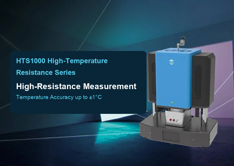
The MatMeas HTS-1000HR High-Temperature High-Resistance Measurement System is engineered specifically for functional ceramics from room temperature up to 800 C. It features a sealed sample chamber supporting vacuum and inert gas purge, preventing atmospheric moisture and electrode oxidation. Its triaxial guarding system enables measurement of extreme insulation resistances spanning 10^3 ohms to 10^15 ohms, with a delicate 0.25 N mechanical load mechanism designed to prevent fracturing thin ceramic discs.
For ultra-high-temperature refractories, structural ceramics, and aerospace sensor materials requiring characterization up to 1600 C, the MatMeas RMS-1650 Ultra-High-Temperature Resistivity System provides an integrated high-purity alumina muffle chamber and platinum-rhodium guarded electrodes. Its advanced shielding eliminates 50/60 Hz induction noise from high-power furnace heating elements, delivering pristine volume resistivity data under extreme thermal environments.
Best-Practice Laboratory SOP for Volume Resistivity Testing
To achieve audit-grade, reproducible volume resistivity measurements on piezoelectric ceramics:
- Specimen Preparation:
- Fabricate flat disc specimens with parallel faces (parallelism < 5 um across 25 mm diameter).
- Polish both surfaces using diamond suspensions down to 1 um to remove surface micro-cracks and contamination.
- Clean ultrasonically in acetone, isopropanol, and deionized water, followed by vacuum drying at 120 C for 2 hours.
- Electrode Application:
- Apply thin-film gold or platinum electrodes (thickness 100 nm to 200 nm) using magnetron sputtering through a precision stainless steel shadow mask.
- Strictly adhere to ASTM D257 guarded geometry: ensure the guard gap width g is uniform and satisfies g <= 2 * specimen thickness d.
- Ensure the outer diameter of the unguarded bottom electrode extends beyond the outer perimeter of the top guard ring.
- Electrometer and Fixture Guarding:
- Mount the specimen in a shielded, triaxial test fixture.
- Connect the central measuring electrode to the electrometer via a low-noise, graphite-lubricated triaxial cable. Connect the guard ring directly to the inner triaxial shield (virtual ground guard).
- Pre-Test Environmental Stabilization:
- Evacuate the chamber or purge with dry nitrogen for 30 minutes to reduce relative humidity below 20%.
- In variable-temperature testing, allow at least 15 minutes of isothermal dwell at each thermal setpoint before applying voltage.
- Voltage Application and 60-Second Electrification:
- Apply a stable DC test voltage corresponding to a field strength of 100 V/mm to 500 V/mm (within the linear ohmic regime).
- Monitor current continuously. Record the formal volume current exactly at t = 60 seconds (I_60s).
- Calculate volume resistance R_v = V_applied / I_60s and compute volume resistivity rho_v = R_v * (A_eff / d).
- Discharge and Depolarization:
- Ground the specimen electrodes through a 100-kiloohm current-limiting resistor for at least 4 times the electrification time (minimum 4 minutes) to completely discharge trapped dielectric absorption charges before initiating subsequent tests.
Frequently Asked Questions (FAQ)
Why must volume resistivity be measured at exactly 60 seconds of electrification time?
When a DC voltage is applied across a dielectric, the measured current is not constant; it decays over several decades of time due to dielectric absorption (Curie-von Schweidler relaxation) and defect dipole polarization. Reading current at 5 seconds captures large transient absorption currents, resulting in an artificially low resistivity value. Conversely, waiting hours for complete steady-state current is impractical in standard industrial quality control. International standards (ASTM D257 and IEC 62631-3-1) standardized 60 seconds as the consensus benchmark where fast polarization processes have completed, providing a reproducible basis for cross-laboratory comparison.
Can volume resistivity be extracted from low-frequency AC impedance spectroscopy?
Yes. In an Electrochemical Impedance Spectroscopy (EIS) Nyquist plot (-Z'' versus Z'), the low-frequency intercept of the bulk semicircle on the real axis represents the bulk DC resistance (R_bulk). Dividing R_bulk by specimen geometry (rho = R_bulk * A / d) yields the volume resistivity. However, for highly insulating piezoelectric ceramics at room temperature (rho_v > 10^13 ohm-cm), the characteristic RC time constant of the material exceeds hundreds of seconds, shifting the bulk semicircle zenith below 1e-4 Hz. Measuring a full impedance arc would take several days per sample. Direct-current electrometer measurement with a guarded electrode is far faster and more accurate for ultra-high-resistance materials.
How does the guard ring eliminate surface leakage without distorting the bulk electric field?
The guard ring is maintained at the identical potential (virtual ground, 0.00 V) as the central measuring electrode by connecting it to the active shield of the electrometer operational amplifier. Because both electrodes share the exact same potential, the lateral potential gradient across the annular gap is virtually zero (Delta V = 0), preventing surface leakage current from crossing into the measuring electrode. Simultaneously, the measuring electrode is much larger than the specimen thickness, ensuring that the electric field lines in the central bulk volume remain strictly parallel and uniform.
Related Instruments & Equipment
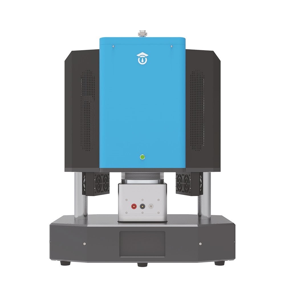
HTS1000HR High Temperature Resistivity Measurement System
The HTS1000HR is an advanced, integrated testing platform specifically engineered to precisely evaluate the electrical conductivity and insulation properties of advanced materials at extreme temperatures up to 800℃. By supporting various atmospheric conditions and offering an ultra-wide resistance measurement range, it serves as an indispensable characterization tool for material research and industrial quality control.
View details →
RMS1650 Ultra-High Temperature Resistivity Measurement System
The RMS1650 Ultra-High Temperature Resistivity Measurement System is engineered for the rigorous electrical characterization of insulating and dielectric materials up to 1600°C. Utilizing a proprietary guarded three-terminal electrode configuration, the system enables in-situ acquisition of resistivity and leakage current kinetics under extreme temperatures, vacuum, and controlled gas atmospheres.
View details →Request High-Precision Testing Solutions
Get expert guidance and customized instruments for your functional materials project.