PUND Testing of Switching Polarization in Ferroelectric Ceramics
Technical News
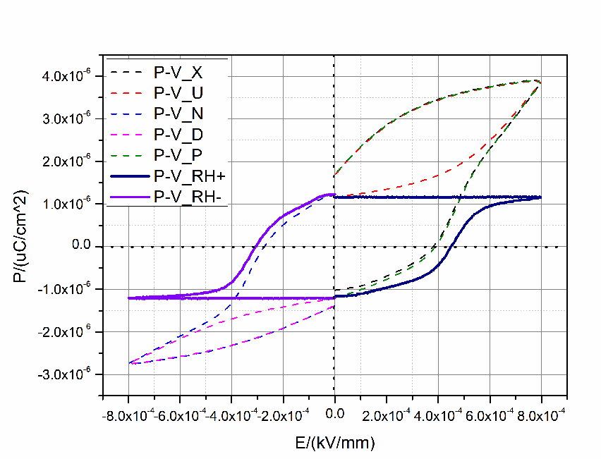
Ferroelectric materials possess spontaneous, bistable electrical polarization that can be repeatedly reoriented between two or more crystallographic states by an externally applied electric field. The magnitude of charge retained upon removing the electric field—remanent polarization (P_r)—serves as the foundational operating mechanism for non-volatile ferroelectric random-access memories (FeRAM), emerging neuromorphic synaptic crossbar arrays, piezoelectric micro-actuators, and advanced electro-optic modulators.
Historically, ferroelectricity has been characterized using continuous bipolar polarization-electric field (P-E) hysteresis loop measurements, traditionally executed using classical Sawyer-Tower analog circuits or continuous triangular-wave transimpedance electrometer circuits. However, as ferroelectric research has shifted toward sub-micron thin films, doped binary oxides (such as fluorite-structured Si:HfO2 and Al:HfO2), and narrow-bandgap multiferroic ceramics (such as BiFeO3), continuous P-E loop characterization encounters a critical failure mode: lossy conductive leakage.
In leaky thin films and lossy ceramics, continuous electric fields generate substantial ohmic, Poole-Frenkel, and space-charge-limited leakage currents. When continuous time-integration circuits integrate these leakage currents over full triangular-wave cycles, the resulting P-E loop displays rounded, swollen "banana-shaped" artifacts. These parasitic loops can easily mislead researchers into reporting massive apparent remanent polarization in materials that are completely non-ferroelectric.
To overcome this fundamental metrological limitation, the Positive-Up-Negative-Down (PUND) pulsed testing protocol—governed by IEEE Std 180 and ASTM F668—has emerged as the definitive global standard. By applying a sequenced train of discrete, microsecond-duration unipolar voltage pulses, PUND physically and mathematically subtracts non-switching parasitic leakage and linear dielectric capacitive displacement, extracting the pristine, true switchable polarization charge.
Operating Mechanism of the Five-Pulse PUND Sequence
The PUND method operates on a simple physical reality: ferroelectric domain switching is a bistable, hysteretic phenomenon that occurs only once when an electric field is applied opposite to the existing polarization direction. Conversely, linear dielectric displacement (Q_linear = C * V) and ohmic leakage conduction (I_leak = V / R) occur identically every time a voltage pulse is applied, irrespective of domain orientation history.
A complete standardized PUND measurement cycle consists of five sequential voltage pulses separated by defined relaxation dwell intervals:
-
Preset (Initialization) Pulse (-V_max): A negative conditioning pulse applied to align all ferroelectric dipoles into a well-defined negative remanent polarization state (-P_r). Following the termination of this preset pulse, the material relaxes for a delay time t_delay (typically 1 ms to 100 ms) under short-circuit conditions, settling into a stable negative baseline.
-
Positive Pulse (P Pulse, +V_max): A positive unipolar pulse of identical peak amplitude +V_max is applied. Because the material was initialized in the -P_r state, this positive field drives full 180-degree domain reversal toward +P_sat. The total integrated charge Q_P recorded during the P pulse represents three concurrent physical contributions:
Q_P = Q_sw + Q_linear + Q_leak
Where Q_sw is the genuine ferroelectric domain switching charge, Q_linear is the linear dielectric capacitive charging, and Q_leak is the integrated leakage current traversing the specimen during pulse duration t_w.
-
Up Pulse (U Pulse, +V_max): Following another relaxation interval t_delay (during which the material settles into its positive remanent state +P_r), a second, identical positive voltage pulse +V_max is applied. Because all switchable ferroelectric domains are already oriented along the positive direction, zero domain reversal occurs (Q_sw = 0). Consequently, the total integrated charge Q_U captures only the non-switching background:
Q_U = Q_linear + Q_leak
By subtracting Q_U from Q_P, the linear capacitance and resistive leakage terms cancel out completely, isolating the pure positive switchable charge delta_Q_P:
delta_Q_P = Q_P - Q_U = Q_sw = 2 * P_r * A
-
Negative Pulse (N Pulse, -V_max): A negative voltage pulse -V_max is applied. Because the domains were left in the +P_r state by the preceding U pulse, this negative field forces full domain reversal back to -P_sat. The integrated charge Q_N again captures switching, dielectric, and leakage components:
Q_N = Q_sw_neg + Q_linear + Q_leak
-
Down Pulse (D Pulse, -V_max): After a relaxation delay, an identical negative pulse -V_max is delivered. Domains are already pointing negative, so no switching occurs:
Q_D = Q_linear + Q_leak
Subtracting Q_D from Q_N isolates the pure negative switchable charge delta_Q_N:
delta_Q_N = Q_N - Q_D = Q_sw_neg = 2 * P_r * A
Mathematical Formulation of PUND Polarization and Memory Margins
In standardized ferroelectric memory metrology (IEEE Std 180), the primary figure of merit extracted from PUND testing is the non-volatile memory switching charge window delta_P:
delta_P = P* - P^ = (Q_P - Q_U) / A
Where:
- P*: The total polarization response measured during the switching P pulse (P* = Q_P / A).
- P^: The non-switching background polarization measured during the non-switching U pulse (P^ = Q_U / A).
- A: The active electrode area of the ferroelectric capacitor.
- delta_P: The net switchable polarization, which equals exactly twice the remanent polarization for fully saturated symmetric switching (delta_P = 2 * P_r).
Dividing delta_P by 2 yields the true, leakage-free remanent polarization P_r:
P_r = (Q_P - Q_U) / (2 * A)
Merz's Law and Switching Kinetics
The duration of the applied PUND pulses (t_w) must be carefully matched to the intrinsic domain nucleation and growth kinetics of the ferroelectric material. Under Merz's classical phenomenological model, the switching time t_sw required for 180-degree domain wall propagation across a crystalline thickness d is dictated by the applied electric field E:
t_sw = t_0 * exp(alpha_E / E)
Where t_0 is a limiting switching time (governed by acoustic phonon velocities, typically 10^-10 s to 10^-11 s), and alpha_E is the activation field required to nucleate reversed domain seeds. If the applied PUND pulse width t_w is shorter than t_sw, domain switching will be incomplete (sub-loop switching), leading to an artificial underestimation of P_r. Conversely, if t_w is set excessively long (e.g., milliseconds), thermal Joule heating and time-dependent space-charge migration will degrade measurement accuracy.
Continuous P-E Hysteresis vs. 5-Pulse PUND Metrology
To illustrate why PUND has superseded conventional continuous triangular loops for advanced materials qualification, the engineering characteristics of both methods are contrasted below.
| Metrological Parameter | Conventional Continuous Bipolar Hysteresis (P-E Loop) | 5-Pulse PUND Metrological Sequence |
|---|---|---|
| Excitation Waveform | Continuous AC sinusoidal or triangular bipolar wave (typically 1 Hz to 10 kHz) | Sequence of five discrete unipolar trapezoidal pulses (Preset, P, U, N, D) |
| Leakage Isolation Mechanism | None; integrates all continuous conduction currents into apparent polarization | Differential subtraction of identical non-switching pulse cancels leakage algebraically |
| Linear Dielectric Rejection | Slanted loop requires manual tilt correction or mathematical capacitance subtraction | Automatic algebraic cancellation; U and D pulses capture pure dielectric charge Q_linear |
| False Ferroelectricity Artifacts | High risk; lossy conductive resistors produce swollen "banana-shaped" loops | Zero risk; pure resistors yield Q_P = Q_U, resulting in delta_P = 0 (correct negative result) |
| Minimum Pulse Resolution | Limited by generator settling time; typically > 100 us per full cycle | Ultra-fast unipolar pulses down to 2 us (and sub-microsecond in advanced analyzers) |
| FeRAM Logic Margin Extraction | Indirect extrapolation from remanent intercepts (+P_r, -P_r) | Direct quantitative readout of non-volatile read/write switching charge delta_Q_sw |
| Dielectric Thermal Stress | Continuous high-voltage cycling causes severe self-heating in lossy thin films | Low duty cycle (< 1%) minimizes specimen Joule heating and prevents thermal breakdown |
| Primary Standard Compliance | General materials screening; prone to misinterpretation in leaky specimens | Mandated by IEEE Std 180 and ASTM F668 for non-volatile memory qualification |
Material Benchmark Comparison: PUND Parameters Across Ferroelectric Classes
The following benchmark table details typical PUND switching polarizations, coercive fields, switching speeds, and endurance limits across major functional ferroelectric families.
| Ferroelectric Material Class | Representative Formulation & Scale | Coercive Field E_c (kV/cm) | PUND True Remanent P_r (uC/cm2) | PUND Switchable delta_P (uC/cm2) | Intrinsic Switching Time t_sw | Maximum Fatigue Endurance (Cycles) | Target High-Value Application Envelope |
|---|---|---|---|---|---|---|---|
| Doped Hafnia Thin Film | 10 nm Si:HfO2 / HZO (ALD-grown) | 1200 to 1800 | 18 to 28 | 36 to 56 | 10 ns to 50 ns | 10^10 to 10^12 | CMOS-compatible embedded FeRAM, neuromorphic crossbars, FeFET logic |
| Lead Zirconate Titanate | PZT 52/48 (1 um sol-gel film) | 40 to 75 | 25 to 35 | 50 to 70 | 50 ns to 200 ns | 10^8 to 10^10 | Standalone commercial FeRAM, piezoelectric MEMS micromirrors, inkjets |
| Lead-Free Perovskite | (K,Na)NbO3 (KNN) Bulk Ceramic | 12 to 18 | 20 to 26 | 40 to 52 | 1 us to 5 us | 10^7 to 10^8 | Eco-compliant medical ultrasound, high-power lead-free ultrasonic transducers |
| Bismuth Layered Aurivillius | SrBi2Ta2O9 (SBT) Thin Film | 50 to 80 | 8 to 12 | 16 to 24 | 100 ns to 500 ns | > 10^12 (Fatigue-free) | Radiation-hardened military aerospace non-volatile memory registers |
| Multiferroic Oxide | BiFeO3 (BFO) Epitaxial Film | 150 to 300 | 60 to 95 | 120 to 190 | 20 ns to 100 ns | 10^6 to 10^7 (Leakage prone) | Spintronic spin-orbit logic, magnetoelectric sensors, photovoltaics |
| Organic Ferroelectric | P(VDF-TrFE) 70/30 Copolymer | 450 to 600 | 6 to 9 | 12 to 18 | 1 us to 10 us | 10^5 to 10^6 | Flexible organic electronics, rollable sensors, bio-integrated wearables |
Hardware Instrumentation: MatMeas FEA-1000 and FMS-1000
Executing reproducible PUND measurements requires instrumentation capable of synthesizing fast, flat-topped trapezoidal voltage pulses while simultaneously acquiring transient displacement currents across six decades of dynamic range.
The MatMeas FEA-1000 High-Precision Ferroelectric Analyzer provides a dedicated hardware platform engineered specifically for high-speed PUND characterization. Operating with an internal high-voltage arbitrary waveform generator, the FEA-1000 delivers unipolar PUND pulses with a minimum pulse width of 2 us and rise times under 1 us, preventing thermal relaxation artifacts from obscuring ultra-fast domain switching in nanoscale HfO2 and PZT thin films. Unlike legacy measurement systems that require cumbersome external pulse generators, the FEA-1000 integrates complete PUND execution, pulse parameter programming, and differential subtraction algorithms natively into its control firmware.
Crucially, testing thin-film capacitors under high electric fields (often exceeding 2 MV/cm) entails a severe risk of dielectric breakdown. When a sample punctures, imported legacy analyzers often suffer catastrophic damage as the full high-voltage rail discharges directly into the sensitive virtual-ground electrometer. The FEA-1000 resolves this hazard through a proprietary ultrafast high-voltage breakdown protection module that clamps input lines within microseconds of a sample puncture, protecting the electrometer from destructive voltage spikes.
For variable-temperature ferroelectric spectroscopy and cryogenic-to-high-temperature domain dynamics, the MatMeas FMS-1000 Ferroelectric Measurement Spectrometer extends PUND characterization from -160 C up to +800 C. The FMS-1000 features zero-phase-shift transimpedance amplifiers and real-time dynamic leakage compensation algorithms, allowing researchers to evaluate remanent polarization and fatigue kinetics under exact in-service thermal profiles.
Standardized Step-by-Step SOP for PUND Testing
To obtain standardized, publication-grade PUND data complying with IEEE Std 180 and ASTM F668, testing personnel should follow this structured testing SOP:
Step 1: Capacitor Fabrication and Inspection
- Fabricate thin-film or bulk ferroelectric capacitors with top and bottom metallic electrodes (recommended top contact diameter 50 um to 200 um for thin films to minimize RC time constants).
- Inspect the electrode perimeter under optical microscopy to confirm clean, burr-free edges.
- Clean the specimen in an ultrasonic bath using electronic-grade isopropanol, dry with high-purity nitrogen, and bake at 100 C for 20 minutes to eliminate adsorbed surface moisture.
Step 2: Preliminary Low-Field Profiling
- Mount the specimen in a shielded probe station or test fixture. Connect triaxial cables to the FEA-1000 analyzer.
- Measure small-signal capacitance C_0 and loss tangent tan delta at 10 kHz under a 50 mV AC bias using an impedance analyzer to confirm baseline device integrity.
- Calculate the geometric RC time constant (tau = R_source * C_0). Ensure that the programmed PUND pulse rise time t_rise is at least five times greater than tau to prevent instrumental ringing.
Step 3: Programming PUND Pulse Timing and Amplitude
- Set the peak pulse voltage V_max such that the resulting electric field E_max exceeds 1.5 to 2.0 times the anticipated coercive field E_c, ensuring complete ferroelectric domain saturation without exceeding the dielectric breakdown threshold.
- Program pulse width t_w (recommended: 2 us to 10 us for thin films; 100 us to 1 ms for bulk ceramics).
- Set the inter-pulse relaxation delay time t_delay (recommended: 1 ms to 10 ms) to ensure complete decay of geometric capacitive charges.
Step 4: Execution and Automated Differential Analysis
- Initiate the automated 5-pulse sequence: Preset -> Delay -> P -> Delay -> U -> Delay -> N -> Delay -> D.
- Monitor real-time current waveforms I(t) across each pulse. Verify that the current returns to baseline zero before the end of the pulse plateau.
- The software executes automated differential integration, calculating Q_sw_pos = Q_P - Q_U and Q_sw_neg = Q_N - Q_D.
- Extract the true remanent polarization P_r and display the net non-volatile memory charge delta_P.
Frequently Asked Questions (FAQ)
Why does a conventional P-E hysteresis loop fail on lossy or leaky ferroelectric thin films?
Continuous P-E hysteresis loops rely on continuous time integration of the current passing through the specimen. If the material exhibits electrical leakage (due to oxygen vacancies, grain boundary defects, or narrow bandgaps), this leakage current is continuously integrated along with the polarization charge. This inflates the calculated polarization, creating distorted "banana-shaped" loops that falsely indicate ferroelectric switching in purely lossy resistors.
What is the mathematical principle that allows PUND to eliminate leakage currents?
PUND applies pairs of identical unipolar pulses (P followed by U). The P pulse captures domain switching, linear capacitance, and leakage: Q_P = Q_sw + Q_linear + Q_leak. The subsequent U pulse captures only linear capacitance and leakage: Q_U = Q_linear + Q_leak, because the domains are already fully switched. Subtracting Q_U from Q_P algebraically cancels both Q_linear and Q_leak, leaving strictly the pure ferroelectric switching charge Q_sw.
What occurs if the programmed PUND pulse width t_w is set too short?
If the pulse width t_w is shorter than the intrinsic domain nucleation and propagation time t_sw (governed by Merz's law), only a fraction of the ferroelectric domains will reverse orientation before the pulse terminates. This partial switching results in an artificially depressed measured remanent polarization P_r. The pulse width must be systematically increased until the extracted delta_P reaches a stable saturation plateau.
How does the FEA-1000 protect against catastrophic instrument damage when thin films puncture?
Testing sub-micron thin films at high electric fields entails a substantial risk of dielectric breakdown. When a sample punctures, it creates a short-circuit arc that discharges the high-voltage supply directly into the electrometer. The FEA-1000 incorporates an ultrafast hardware protection circuit that detects current spikes within microseconds and clamps the output lines, isolating sensitive electrometer stages and preventing hardware destruction.
Related Instruments & Equipment
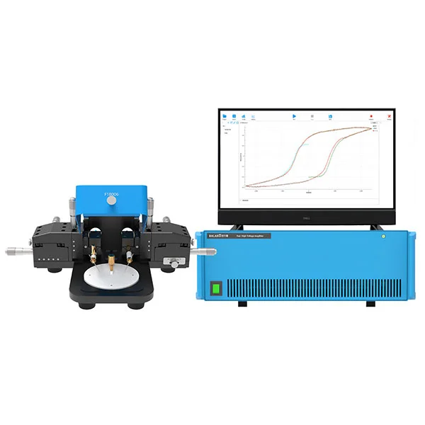
MatMeas FEAI1000 High-Precision Ferroelectric Analyzer
The MatMeas FEAI1000 is an advanced High-Precision Ferroelectric Analyzer specifically engineered for the rigorous evaluation of ferroelectric thin-film materials. Equipped with a built-in or external ±100V high-voltage amplifier, it delivers exceptional accuracy in measuring P-E hysteresis loops, spontaneous polarization, and leakage currents. Designed with proprietary high-voltage breakdown protection, it completely prevents the common catastrophic failures seen in traditional imported models. Offering measurement fidelity that directly rivals the German aixACCT TF2000 and surpassing the PolyK LY20, the FEAI1000 is the ultimate cost-effective infrastructure for dielectric functional ceramics research.
View details →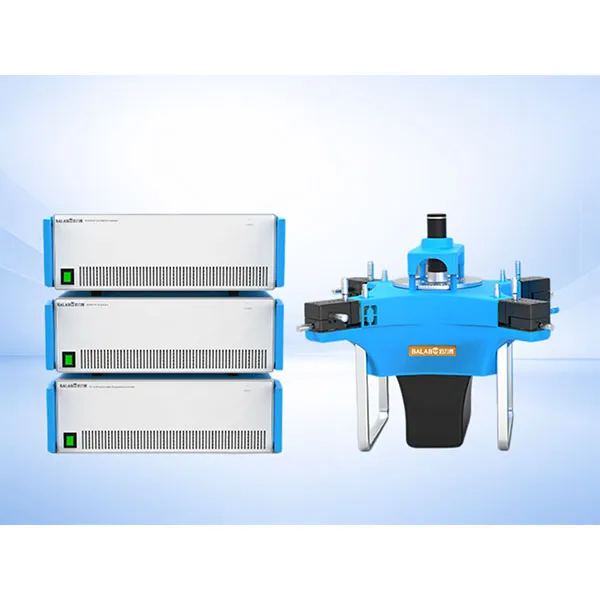
MatMeas FMS Ferroelectric Measurement Spectrometer
MatMeas High‑precision ferroelectric measurement system for hysteresis loop, fatigue testing and leakage current analysis under extreme temperatures.
View details →Request High-Precision Testing Solutions
Get expert guidance and customized instruments for your functional materials project.