High-Temperature Electrical Resistivity Testing of Graphite Materials
Technical News
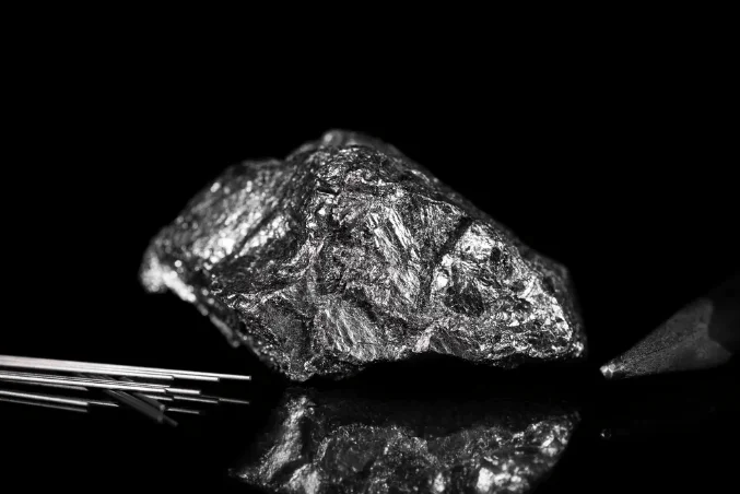
Manufactured graphite and carbonaceous materials possess an exceptional combination of physical properties: sublimate temperatures exceeding 3600 C, excellent thermal shock resistance, low thermal expansion, increasing mechanical strength with temperature up to 2500 C, and semi-metallic electrical conductivity. Consequently, bulk graphite serves as the foundational material for high-temperature resistance heaters, electric arc furnace (EAF) electrodes, electrical discharge machining (EDM) dies, continuous casting dies, high-temperature gas-cooled reactor (HTGR) nuclear core moderator blocks, and semiconductor crystal pulling crucibles.
In all these high-temperature applications, electrical resistivity (rho, expressed in micro-ohm-meters, uOhmm, or ohmcm) is the governing parameter. It dictates ohmic power dissipation (P = I^2 * R), current density distribution, thermal gradient generation, and energy consumption.
However, characterizing the electrical resistivity of bulk graphite across an extended thermal domain—from ambient room temperature up to +1000 C or +1600 C—presents severe experimental difficulties that frequently invalidate conventional measurement setups:
- Catastrophic Atmospheric Oxidation: In the presence of ambient oxygen, carbonaceous materials begin rapid, irreversible oxidation above 450 C, consuming the sample matrix into CO and CO2 gases.
- Extreme Seebeck Thermoelectric Offsets (Thermal EMF): Even minor temperature gradients within a furnace hot zone generate tens to hundreds of microvolts of thermoelectric potential at graphite-metal probe junctions, swamping true micro-ohm potential drops.
- Complex Non-Monotonic Temperature Coefficients: Unlike simple metals, graphite exhibits a non-linear resistance-temperature profile, transitioning from negative temperature coefficient (NTC) behavior at low-to-intermediate temperatures to positive temperature coefficient (PTC) behavior at high temperatures.
Achieving publication-grade, traceable characterization requires pairing rigorous specimen geometry conforming to ASTM C611 and DIN 51911 with active atmosphere control and dynamic thermal EMF cancellation.
The Physics of Non-Monotonic Electrical Resistivity in Graphite
The temperature dependence of electrical resistivity in synthetic polycrystalline graphite differs fundamentally from conventional metals. In pure metals (such as copper or platinum), the density of free conduction electrons remains essentially constant with temperature, while increased lattice thermal vibrations (acoustic phonons) scatter electrons. Consequently, metallic resistivity increases monotonically with temperature following Matthiessen's rule (positive temperature coefficient of resistance, PTC).
In contrast, graphite is a semi-metal with a zero or diminutive energy bandgap, where the valence and conduction bands overlap slightly at the corners of the hexagonal Brillouin zone. Its electrical resistivity as a function of temperature is dictated by two competing physical mechanisms:
-
Thermally Activated Carrier Generation (Low to Intermediate Temperatures, 25 C to ~500 C): At ambient temperatures, the intrinsic free carrier concentration in graphite is relatively low (~10^18 to 10^19 cm^-3). As temperature increases, thermal excitation promotes valence electrons across the band overlap into the conduction band, creating equal concentrations of mobile electrons and holes. Because carrier density increases faster than phonon scattering reduces mobility, the electrical resistivity of the material initially decreases with increasing temperature:
d(rho) / dT < 0 (Negative Temperature Coefficient, NTC regime)
-
Lattice Phonon Scattering (High Temperatures, > 500 C to 1000 C+): As the temperature exceeds an inflection point T_min (typically between 400 C and 600 C for high-density isotropic graphite), carrier concentration approaches saturation. Beyond this threshold, intense thermal vibrations of the carbon crystalline lattice cause severe acoustic phonon scattering, dramatically shortening carrier mean free path:
d(rho) / dT > 0 (Positive Temperature Coefficient, PTC regime)
The overall temperature dependence of resistivity across a 25 C to 1000 C sweep is typically modeled using a second-order polynomial formulation:
rho(T) = rho_0 * [1 + alpha_1 * (T - T_0) + beta_1 * (T - T_0)^2]
Where rho_0 is the baseline resistivity at reference temperature T_0 (25 C), alpha_1 is the linear temperature coefficient (negative in sign), and beta_1 is the quadratic coefficient (positive in sign). Identifying the precise inflection temperature T_min is vital for thermal-electric modeling of furnace heating elements to prevent localized current-crowding hot spots.
Material Benchmark Comparison: Graphite Grades Across Temperature
The following benchmark table illustrates the non-monotonic resistivity curves, inflection temperatures, and oxidation boundaries across leading industrial and nuclear graphite formulations.
| Graphite Material Grade | Forming Method & Microstructure | Room-Temp Resistivity rho at 25 C (uOhm*m) | Inflection Temp T_min (NTC to PTC) | High-Temp Resistivity at 1000 C (uOhm*m) | Net Change from 25 C to 1000 C | Oxidation Threshold in Air | Primary High-Temperature Engineering Application |
|---|---|---|---|---|---|---|---|
| Nuclear Grade IG-110 | Isostatically pressed, ultra-fine grain | 10.5 to 11.5 | ~450 C | 12.8 to 13.5 | +18% to +22% | ~450 C | Core moderator and structural reflector bricks in HTGR nuclear reactors |
| EDM Die Grade (Poco ZXF) | Fine-grained, isotropic, high-density | 14.5 to 16.0 | ~500 C | 16.5 to 17.8 | +10% to +14% | ~480 C | Precision electrical discharge machining dies, aerospace hot-gas valves |
| Extruded Electrode Graphite | Coarse-grained, anisotropic | 7.0 to 8.5 (parallel) | ~400 C | 8.8 to 10.2 | +20% to +25% | ~420 C | Electric arc furnace (EAF) steel smelting melting electrodes |
| Vibrated Large-Billet Graphite | Medium-grained, molded carbon | 9.0 to 11.0 | ~420 C | 11.5 to 13.0 | +22% to +28% | ~440 C | Photovoltaic Cz silicon pulling heaters, vacuum sintering heating cages |
| Flexible Expanded Graphite Foil | Exfoliated natural flake (calendared) | 7.5 to 9.0 (in-plane) | ~350 C | 10.5 to 12.5 | +35% to +45% | ~400 C | Ultra-high temperature vacuum furnace insulation shields, expansion gaskets |
| Glassy (Vitreous) Carbon | Impermeable disordered carbon matrix | 40.0 to 50.0 | > 800 C | 38.0 to 45.0 | -8% to -12% (NTC) | ~520 C | Semiconductor processing boats, molten salt electrolysis crucibles |
ASTM C611 Kelvin Four-Terminal Bar Metrology and Geometric Constraints
When evaluating bulk graphite rods, machined rectangular billets, or large test coupons, ASTM C611 mandates the Kelvin four-terminal bar configuration.
A regulated direct current I is introduced through two full-face current contacts at the extreme ends of the specimen. Two knife-edge or point-contact potential probes are positioned along the gauge length L at the center of the bar to sense the voltage drop delta_V:
rho = (delta_V / I) * (A / L) = (delta_V / I) * (w * t / L)
Where:
- w: The measured width of a rectangular specimen (meters).
- t: The measured thickness of a rectangular specimen (meters).
- A: The uniform cross-sectional area (w * t for rectangular bars, or pi * r^2 for cylindrical rods).
- L: The precise distance between the knife-edge potential sensing taps.
Elimination of Current Crowding and Geometric Aspect Ratios
To ensure that the measured voltage drop accurately reflects bulk material resistivity, electrical current streamlines must become perfectly parallel and uniformly distributed across the entire cross-section before reaching the potential taps.
If the potential taps are placed too close to the end current injection electrodes, non-uniform current injection (current crowding) introduces severe geometrical errors. ASTM C611 establishes strict geometric design rules:
-
Total Specimen Aspect Ratio: The total length of the specimen L_total must be at least five times the square root of the cross-sectional area:
L_total >= 5 * sqrt(A)
-
Buffer Distance: The distance d_in from each outer current contact to the nearest potential tap must exceed 1.5 times the square root of the cross-sectional area:
d_in >= 1.5 * sqrt(A)
-
Gauge Length: The distance L between the potential taps must be at least twice the maximum cross-sectional dimension:
L >= 2 * sqrt(A)
Adhering to these dimensional ratios guarantees that current streamlines are parallel, eliminating geometric fringing errors to under 0.2%.
The Physics of Dynamic Thermal EMF Cancellation in Hot Zones
When testing graphite conductors at temperatures up to 1000 C or 1600 C, the most devastating error source is the Seebeck thermoelectric effect.
Inside any high-temperature furnace, thermal gradients exist across the sample gauge length. Furthermore, graphite has a massive Seebeck coefficient relative to common probe metals (such as platinum, molybdenum, or tungsten). The physical junction between the hot graphite specimen and metallic voltage sensing leads forms an unintentional thermocouple pair. This junction generates an unavoidable Seebeck electromotive force (V_Seebeck):
V_Seebeck = integral_T_cold^T_hot (S_metal(T) - S_graphite(T)) dT
In low-resistance graphite specimens where the true ohmic IR drop (delta_V_true) is only 100 uV to 1 mV, an uncompensated thermal EMF of 50 uV to 300 uV introduces errors of 5% to 50%, and can even produce negative apparent resistance if the thermal gradient opposes current flow.
To eliminate this error, modern automated testing systems employ bipolar delta-mode current reversal. The instrument delivers rapid, alternating current pulses of equal magnitude (+I and -I):
-
Forward Current Step (+I):
V_1 = (+I) * R_x + V_Seebeck
-
Reverse Current Step (-I):
V_2 = (-I) * R_x + V_Seebeck
Subtracting the two voltage measurements completely eliminates the common-mode Seebeck thermoelectric potential:
delta_V_true = (V_1 - V_2) / 2 = I * R_x
R_x = (V_1 - V_2) / (2 * I)
Simultaneously, the true Seebeck thermal EMF can be extracted:
V_Seebeck = (V_1 + V_2) / 2
Executing this bipolar switching at a frequency of 5 Hz to 20 Hz ensures that rapid thermal fluctuations inside the furnace hot zone are rejected in real time.
Metrological Comparison: Four-Terminal Bar vs. Four-Point Probe
The table below provides a side-by-side comparison of the ASTM C611 four-terminal bar method and the collinear four-point probe method for carbonaceous materials.
| Characterization Parameter | ASTM C611 Four-Terminal Bar Method | Collinear Four-Point Probe Method (ASTM F84 / SEMI MF84) |
|---|---|---|
| Specimen Form Factor | Machined rectangular bars, cylindrical rods, extruded billets | Thin foils, exfoliated graphite sheets, flat polished blocks |
| Current Flow Distribution | One-dimensional, uniform parallel streamlines across bulk area A | Two-dimensional cylindrical spreading or 3D hemispherical spreading |
| Geometric Correction Dependency | Zero geometric factor; strictly simple geometry (rho = R * A / L) | Heavy dependence on Smits thickness correction factor F(t / s) |
| Contact Pressure Sensitivity | Low; knife-edges or clamped tabs maintain permanent contact | High; spring-loaded pin force must be strictly regulated |
| Machining Requirements | Strict; requires precision rectangular or cylindrical machining | Minimal; flat as-received or lightly polished surface is sufficient |
| High-Temperature Viability | Exceptional; clamped metallic screws remain stable up to 1600 C | Challenging; thermal expansion can cause needle slipping or wear |
| Primary Standard Applicability | ASTM C611, DIN 51911, ISO 3915 (Bulk Carbon & Graphite) | ASTM F84, SEMI MF84 (Thin conductive sheets and semiconductor wafers) |
Dedicated Instrumentation: MatMeas RTS-1000C and RMS-1000P
Characterizing graphite across broad thermal ranges requires instrumentation engineered specifically to mitigate chemical oxidation and eliminate thermoelectric noise.
The MatMeas RTS-1000C High-Temp Conductive Material Resistivity System (upgraded from the RMS-1000C platform) is purpose-built for bulk graphite blocks, rods, and high-temperature metallic conductors spanning 10 nΩ to 100 MΩ from ambient to 600°C (with custom options up to 1000°C). The RTS-1000C features dense 99% Zirconia (ZrO₂) thermal isolation and a sealed atmosphere chamber supporting high-vacuum evacuation or positive-pressure purge with ultra-pure inert gas (argon or nitrogen). This prevents oxygen from entering the hot zone, completely eliminating sample burn-off. Furthermore, the RTS-1000C integrates automated bipolar current reversal, canceling out Seebeck thermal EMF in real time to deliver true nano-ohm measurement resolution.
For applications involving thin conductive carbon coatings, exfoliated graphite foils, and semiconductor wafer substrates, the MatMeas RMS-1000P High-Temp Four-Point Probe Resistivity System serves as a dedicated characterization platform. The RMS-1000P incorporates a motorized probe head with precision load cell feedback, ensuring repeatable contact force across an ultra-wide resistance range from 0.1 mOhm to 100 MOhm up to +1000 C. To prevent static electricity from damaging delicate carbon nanostructures, the RMS-1000P features active dual-electrostatic discharge (ESD) neutralization, ensuring reliable, non-destructive surface testing.
Standardized Step-by-Step SOP for High-Temperature Graphite Resistivity
To ensure compliant, traceable resistivity testing conforming to ASTM C611 and DIN 51911, testing personnel should enforce this standardized laboratory protocol:
Step 1: Specimen Fabrication and Dimensional Inspection
- Machine graphite test specimens into rectangular bars or cylindrical rods complying with ASTM C611 aspect ratios (L_total >= 5 * sqrt(A)). Recommended dimensions are 10 mm x 10 mm x 100 mm.
- Measure width w, thickness t, or diameter d at five evenly distributed positions along the gauge section using a calibrated digital micrometer; calculate the mean cross-sectional area A (+/-0.1% precision).
- Degrease the sample ultrasonically in acetone for 10 minutes, followed by isopropanol. Dry in an oven at 150 C for 2 hours to eliminate moisture trapped within the open porosity, then cool inside a desiccator.
Step 2: Fixture Mounting and Tap Alignment
- Mount the specimen between the heavy-gauge current injection end-plates of the RTS-1000C fixture. Apply uniform mechanical torque to ensure low contact resistance.
- Position the two high-temperature potential sensing knife-edges along the center gauge length. Measure and record the exact gauge spacing L between the knife-edges using an optical traveling microscope (+/-0.02 mm precision).
- Mount an adjacent shielded thermocouple within 1.0 mm of the central gauge section, ensuring the thermocouple sheath does not electrically contact the graphite bar.
Step 3: Vacuum Chamber Evacuation and Atmospheric Purge
- Close and seal the test chamber. Evacuate using a turbomolecular vacuum pump to a base pressure below 1.0 * 10^-3 Pa.
- If testing under inert gas, backfill the chamber with high-purity argon (99.999% purity) to atmospheric pressure, then establish a continuous purge flow rate of 50 to 100 sccm. Never heat graphite in an unpurged chamber containing residual air.
Step 4: Current Verification and Thermal Execution
- Apply a preliminary DC test current I (typically 100 mA to 1.0 A). Verify that the measured potential drop delta_V is stable and free from AC line noise.
- Activate automated bipolar delta-mode current reversal (+I, -I) and verify that the calculated Seebeck offset V_Seebeck is successfully isolated.
- Program the furnace temperature controller to ramp at a regulated rate (recommended: 3 C/min to 5 C/min) up to the maximum test setpoint (e.g., 1000 C).
- Continuously log temperature T, forward voltage V_1, reverse voltage V_2, true ohmic resistance R_x, and calculated volume resistivity rho across both heating and cooling cycles to verify thermal reversibility.
Frequently Asked Questions (FAQ)
Why does the electrical resistivity of bulk graphite decrease initially before increasing at high temperatures?
Graphite is a semi-metal with a very small band overlap. From room temperature up to ~500 C, thermal excitation promotes electrons into the conduction band, increasing carrier concentration and causing resistivity to decrease (negative temperature coefficient, NTC). Above 500 C to 600 C, carrier generation saturates, and acoustic phonon scattering from thermal lattice vibrations becomes dominant, causing resistivity to increase (positive temperature coefficient, PTC).
How does Seebeck thermal EMF generate measurement errors during high-temperature testing?
When a graphite bar is heated in a furnace, thermal gradients exist along its length. The contact between the graphite sample and metallic measurement probes creates a thermocouple junction that generates an unwanted DC thermoelectric voltage (thermal EMF). In low-resistance measurements where the actual signal is only microvolts, this thermoelectric voltage can equal or exceed the true signal unless high-speed bipolar current reversal is used to mathematically cancel it.
Why is vacuum or high-purity inert gas mandatory when heating graphite above 450 C?
Carbonaceous materials react vigorously with atmospheric oxygen at elevated temperatures: C + O2 -> CO2. Above 450 C in ambient air, graphite rapidly oxidizes, degrading its surface, eroding its cross-sectional area, and eventually destroying the sample. Enveloping the sample in high vacuum (< 10^-3 Pa) or pure argon eliminates oxygen, ensuring complete chemical and dimensional stability up to 1000 C and beyond.
Why must potential taps be separated from current injection contacts by a defined distance in ASTM C611?
When electric current enters the end of a graphite bar through an electrode, the current streamlines diverge and crowd near the edges of the contact. If potential taps are placed too close to the end contacts, they sample this non-uniform current field, resulting in severe geometric calculation errors. ASTM C611 mandates that potential taps be positioned at least 1.5 times the square root of the cross-sectional area away from the current contacts, guaranteeing that streamlines are fully parallel and uniform.
Related Instruments & Equipment
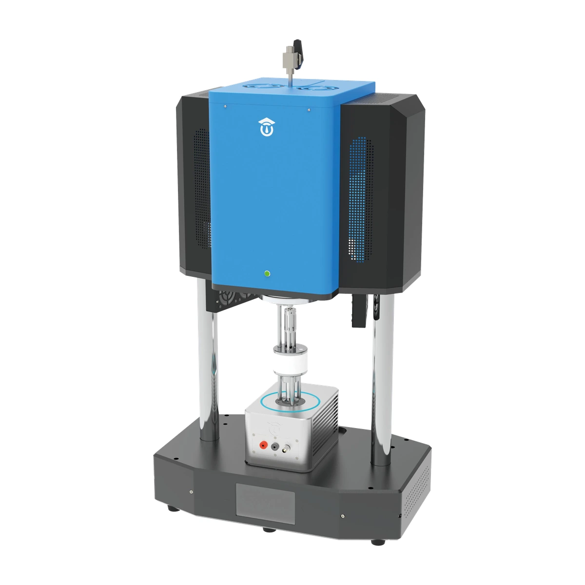
MatMeas RTS-1000C High-Temp Conductive Material Resistivity System (Upgraded from RMS-1000C)
The MatMeas RTS-1000C is the next-generation flagship evolution of the earlier RMS-1000C system, purpose-built for precision high-temperature conductive material resistivity measurement via four-wire Kelvin method. Delivering nΩ-to-MΩ resolution (10 nΩ to 100 MΩ) from RT to 600°C (±1°C PID), the upgraded platform features 99% zirconia thermal isolation, a rigid motorized test stand, and hybrid platinum/tungsten-carbide probes for vacuum and controlled atmospheres.
View details →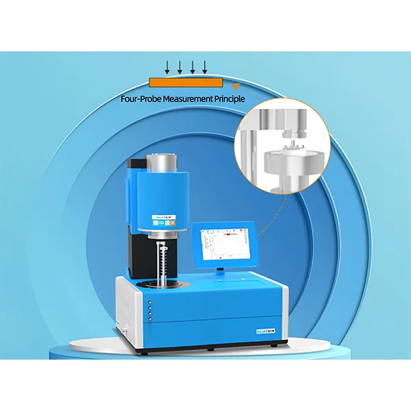
MatMeas RMS-1000P High-Temp Four-Point Probe Resistivity System
RMS-1000P uses four-point probe method for thin film and wafer resistivity measurement, featuring dual-electrostatic measurement, 0.1mΩ~100MΩ range, and specialized fixture for semiconductor materials.
View details →Request High-Precision Testing Solutions
Get expert guidance and customized instruments for your functional materials project.