Piezoelectric Ceramics Electrical Testing and Electromechanical Safety Evaluation
Technical News
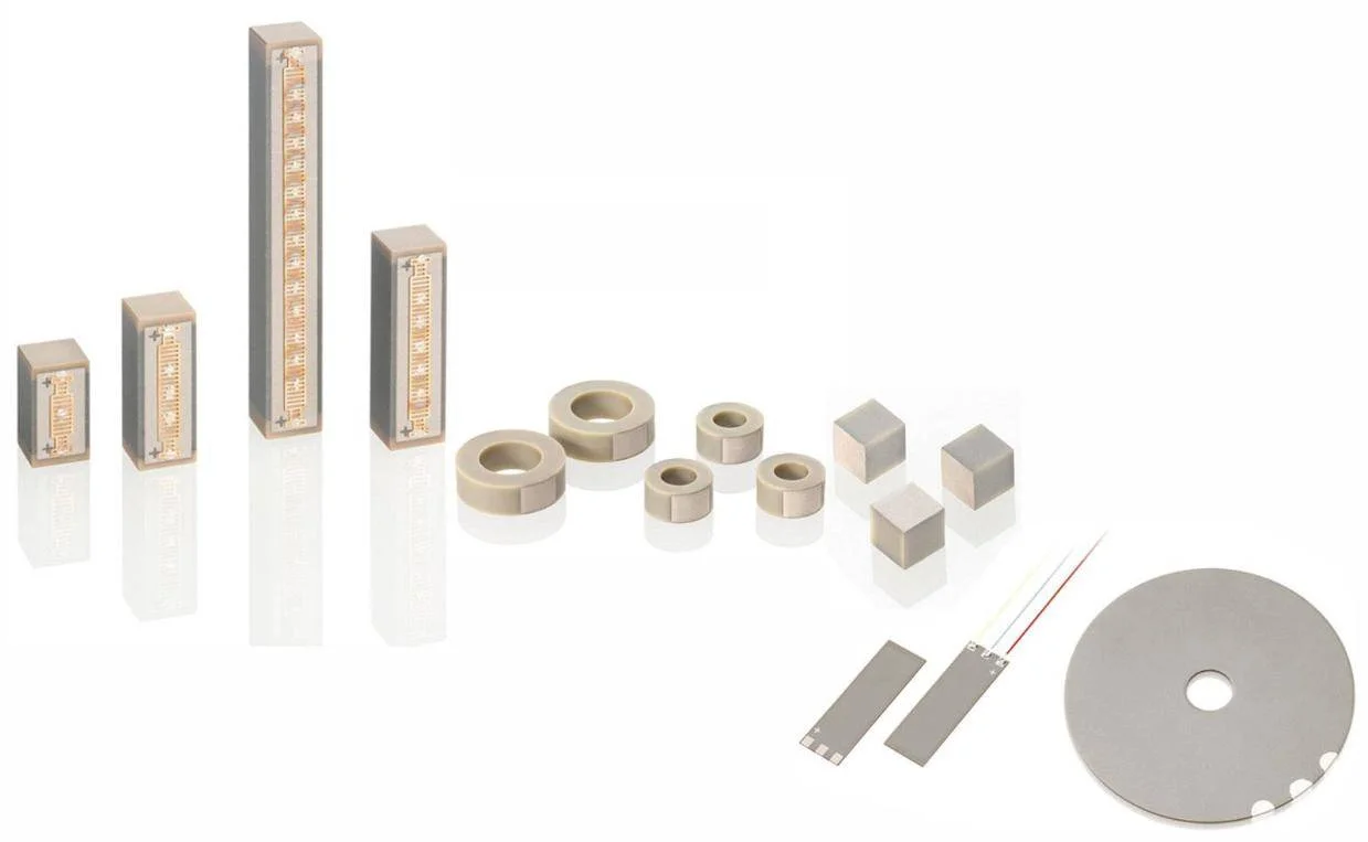
Piezoelectric ceramics deployed in high-power continuous-wave acoustic applications—such as surgical ultrasonic scalpels, industrial ultrasonic welders, subsea sonar projectors, and micro-positioning piezoelectric stack actuators—operate under intense dynamic electromechanical stress. Comprehensive piezoelectric ceramics electrical testing and electromechanical safety evaluation prevent catastrophic thermal runaway and dynamic depoling near fundamental resonance. In these demanding operational regimes, ceramics are driven at electrical field strengths exceeding 500 V/mm and mechanical acoustic stress amplitudes surpassing 50 MPa near fundamental resonance.
Under continuous resonant excitation, standard small-signal electromechanical parameters become invalid. Non-linear ferroelastic domain wall friction and dielectric hysteresis generate severe internal heat dissipation. If thermal generation exceeds heat dissipation capacity, the ceramic enters a self-accelerating cycle of thermal runaway: resonance frequency drifts out of generator matching bandwidth, mechanical quality factor (Qm) collapses, and operating temperatures surge past the depolarization threshold, causing catastrophic loss of piezoelectricity. Establishing electromechanical safety testing protocols is essential to qualify materials for mission-critical industrial applications.
Butterworth-Van Dyke (BVD) Equivalent Circuit and Non-Linear Power Dissipation Physics
The electrical admittance Y( ω) of a piezoelectric ceramic resonator vibrating near an isolated mechanical resonance mode is modeled by the classical Butterworth-Van Dyke (BVD) equivalent circuit under IEEE Std 176, as detailed in our guide on piezoelectric ceramics testing methods and resonance evaluation:
Y( ω) = j · ω · C0 + 1 / [R1 + j · (ω · L1 − 1 / (ω · C1))]
where:
- C0 is the static electrostatic capacitance of the clamped ceramic dielectric,
- C1 is the motional capacitance representing mechanical elastic compliance,
- L1 is the motional inductance representing effective vibrating mass,
- R1 is the motional mechanical resistance representing internal acoustic damping and friction.
The mechanical quality factor Qm, which quantifies the sharpness of the mechanical resonance and mechanical energy storage efficiency, is inversely proportional to motional resistance R1:
Qm = (1 / R1) · (L1 / C1)0.5 = fa² / [2 · π · fr · |Zm| · C0 · (fa² − fr²)]
where fr is the series resonant frequency (admittance maximum), fa is the parallel antiresonant frequency (impedance maximum), and |Zm| is the minimum impedance magnitude.
Under high-power electrical excitation, internal power dissipation density Ploss (in W/cm³) arises from two coupled dissipative mechanisms: dielectric loss and elastic mechanical damping:
Ploss = ω · ε0 · εr · tan δ · Edrive² + (1 / Qm) · ω · sE · Tstress²
- Dielectric Loss Dissipation: Proportional to the dielectric loss tangent tan δ and the square of the applied electric field Edrive.
- Mechanical Acoustic Friction Loss: Proportional to internal mechanical compliance sE, the square of internal acoustic stress Tstress, and inversely proportional to Qm.
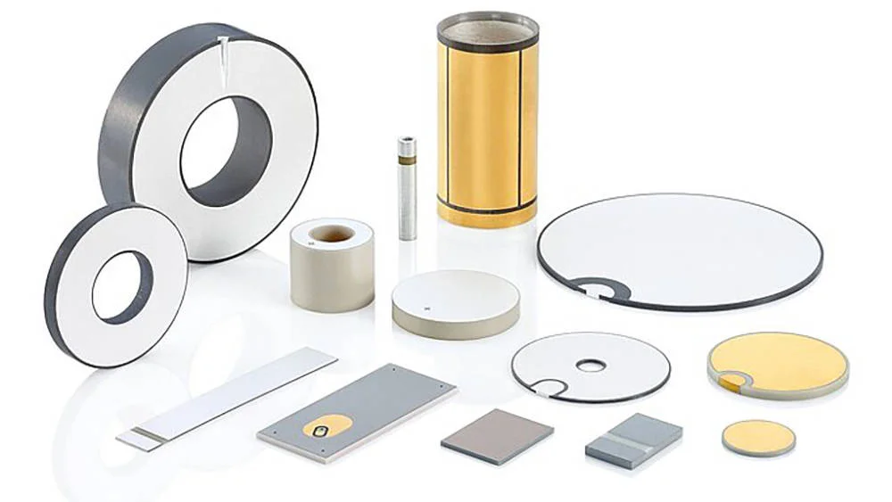
In resonant transducers operating at fr, the mechanical strain is amplified by the mechanical quality factor (Smax ∝ Qm · d33 · E). Consequently, mechanical acoustic damping dominates over 80% to 90% of total internal heat generation. A drop in Qm causes internal heating to escalate, leading to thermal depoling below the nominal threshold established by Curie temperature measurement in piezoelectric ceramics.
Parameter Screening Matrix: Hard PZT vs. Soft PZT Operational Safety Envelopes
High-power electromechanical applications require acceptor-doped "hard" piezoelectric ceramics engineered to pin domain walls, maximize Qm, and stabilize domain configurations against coercive reversal (see piezoelectric ceramic polarization factors).
The screening matrix below compares the operational safety envelopes of standard piezoelectric ceramic formulations under continuous dynamic drive:
| Piezoelectric Ceramic Grade | Formulation Doping Mechanism | Mechanical Quality Factor Qm | Dielectric Loss tan δ (1 kHz, Low Field) | Maximum Allowable Dynamic Stress (MPa) | Coercive Field Ec (kV/mm) | Curie Temperature TC (°C) | High-Power Transducer Suitability |
|---|---|---|---|---|---|---|---|
| Super-Hard PZT-8 (Navy III) | Heavy Fe³⁺/Mn²⁺ acceptor-doped | 1000 to 1500 | < 0.3% | 70 to 90 | 2.2 to 2.6 | 300 to 315 | Excellent: Lowest internal heating; standard for ultrasonic welding |
| Hard PZT-4 (Navy I) | Balanced Fe³⁺ acceptor-doped | 500 to 800 | < 0.5% | 50 to 65 | 1.8 to 2.2 | 320 to 335 | Very Good: High acoustic power output with moderate heat dissipation |
| Soft PZT-5A (Navy II) | Nb⁵⁺/La³⁺ donor-doped | 65 to 85 | 1.5% to 2.0% | 15 to 25 | 1.0 to 1.2 | 350 to 365 | Unsuitable for Resonant Power: Severe thermal runaway within seconds |
| Lead-Free KNN High-Power | Modified (K,Na)NbO3 | 200 to 400 | 0.8% to 1.2% | 30 to 45 | 1.2 to 1.5 | 380 to 410 | Promising: Suitable for moderate acoustic power in medical devices |
Dynamic Safety Failure Modes and IEEE Std 176 Screening Protocols
Comprehensive electromechanical safety qualification under IEEE Std 176 and IEC 60483 requires evaluating ceramics under simulated high-drive conditions and piezoelectric d33 dynamic force testing under cyclic mechanical loads to detect latent failure modes.
The diagnostic failure screening table below outlines critical failure mechanisms and acceptance criteria:
| Electromechanical Failure Mode | Root Physical Trigger | Monitored Metrology Indicator | Acceptance Threshold (IEEE 176 Screening) | Engineering Mitigation Protocol |
|---|---|---|---|---|
| Thermal Runaway & Depoling | High motional resistance R1 driving excessive heat generation | Temperature surge ΔT > 40°C; abrupt drop in kp | Operating temp must remain < TC / 2 under maximum drive | Select high-Qm formulation (Qm > 1000, e.g., PZT-8) |
| Ferroelastic Tensile Fracture | Dynamic acoustic tensile stress exceeding ceramic tensile strength (~30–50 MPa) | Abrupt impedance collapse; visible transverse fracture | Dynamic tensile stress Tdyn must not exceed 25 MPa | Apply compressive static pre-stress (20–40 MPa) via central bolt |
| Electrode Solder Fatigue & Arcing | High-current acoustic shear stress delaminating silver electrode | Visual burning; intermittent electrical short circuit | Solder peel strength > 20 N; electrode tan δ degradation < 5% | Sputter Ni/Au or employ silver-copper alloy braze metallization |
| Resonance Frequency De-Tuning | Elastic softening under high drive (sE increases, shifting fr downward) | Resonant frequency shift Δfr > 5% between low and high drive | Δfr / fr must remain < 2% across full power range | Integrate phase-locked loop (PLL) tracking generator circuitry |
Advanced Transducer Characterization: MatMeas PCA-1000 Analyzer
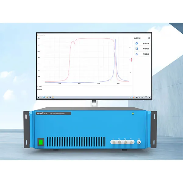
To rigorously quantify dynamic admittance circles, motional parameters, and electromechanical safety envelopes, the MatMeas PCA-1000 Piezoelectric Parameter Analyzer provides an automated testing platform engineered for high-power transducer evaluation.
The PCA-1000 sweeps frequency across user-defined spans (from 10 Hz up to 10 MHz) with multi-point impedance analysis, accurately fitting the complete Butterworth-Van Dyke equivalent circuit (C0, C1, L1, R1) and resolving dynamic admittance circles. Automated algorithms extract resonant and antiresonant frequencies (fr, fa), calculate mechanical quality factor Qm, planar coupling kp, and thickness coupling kt, and monitor motional resistance R1 across variable drive voltages. By tracking parameter stability versus excitation amplitude, the system screens out defective elements before assembly into high-value transducer stacks.
Frequently Asked Questions
Why does a soft PZT ceramic overheat rapidly when driven at mechanical resonance?
Soft PZT ceramics (such as PZT-5A) are donor-doped, creating cation vacancies that unpin ferroelectric domain walls. While this gives soft PZT a high piezoelectric charge coefficient (d33 ≈ 400–500 pC/N), it also introduces massive ferroelastic domain wall friction under alternating dynamic stress. As a result, soft PZT exhibits a very low mechanical quality factor (Qm ≈ 70) and high dielectric loss (tan δ ≈ 2%). Because internal mechanical heat dissipation is inversely proportional to Qm, over 90% of the input acoustic energy is converted into heat, inducing thermal runaway and thermal depoling within seconds of resonant drive.
Why must high-power ultrasonic sandwich transducers (Langevin transducers) incorporate mechanical pre-stress?
Polycrystalline ceramics exhibit high compressive mechanical strength (>500 MPa) but are inherently brittle with low tensile strength (typically 30 to 50 MPa). During resonant longitudinal vibration, acoustic waves generate alternating tensile and compressive stresses within the ceramic rings. If the dynamic tensile stress exceeds the tensile strength of the ceramic, microscopic flaws propagate, causing catastrophic mechanical shattering. Applying an external static compressive pre-stress (typically 20 to 40 MPa via an internal high-tensile steel tie bolt) ensures that the ceramic operates entirely in a compressive stress state throughout the full vibration cycle.
What is the physical significance of motional resistance R1 in the BVD equivalent circuit?
In the Butterworth-Van Dyke (BVD) equivalent circuit, motional resistance R1 represents the real, dissipative component of mechanical acoustic impedance. It accounts for internal acoustic damping, domain wall friction, and acoustic radiation into the surrounding medium. A low R1 indicates low internal mechanical friction and a high mechanical quality factor Qm. A high R1 indicates significant acoustic energy dissipation as internal heat, serving as a primary indicator of transducer inefficiency and thermal instability.
Request High-Precision Testing Solutions
Get expert guidance and customized instruments for your functional materials project.