Electrical Conductivity Testing of Porous 3D-Printed Ceramics: Contact Mechanics & Thermal-EMF (RT–1000°C)
Technical News
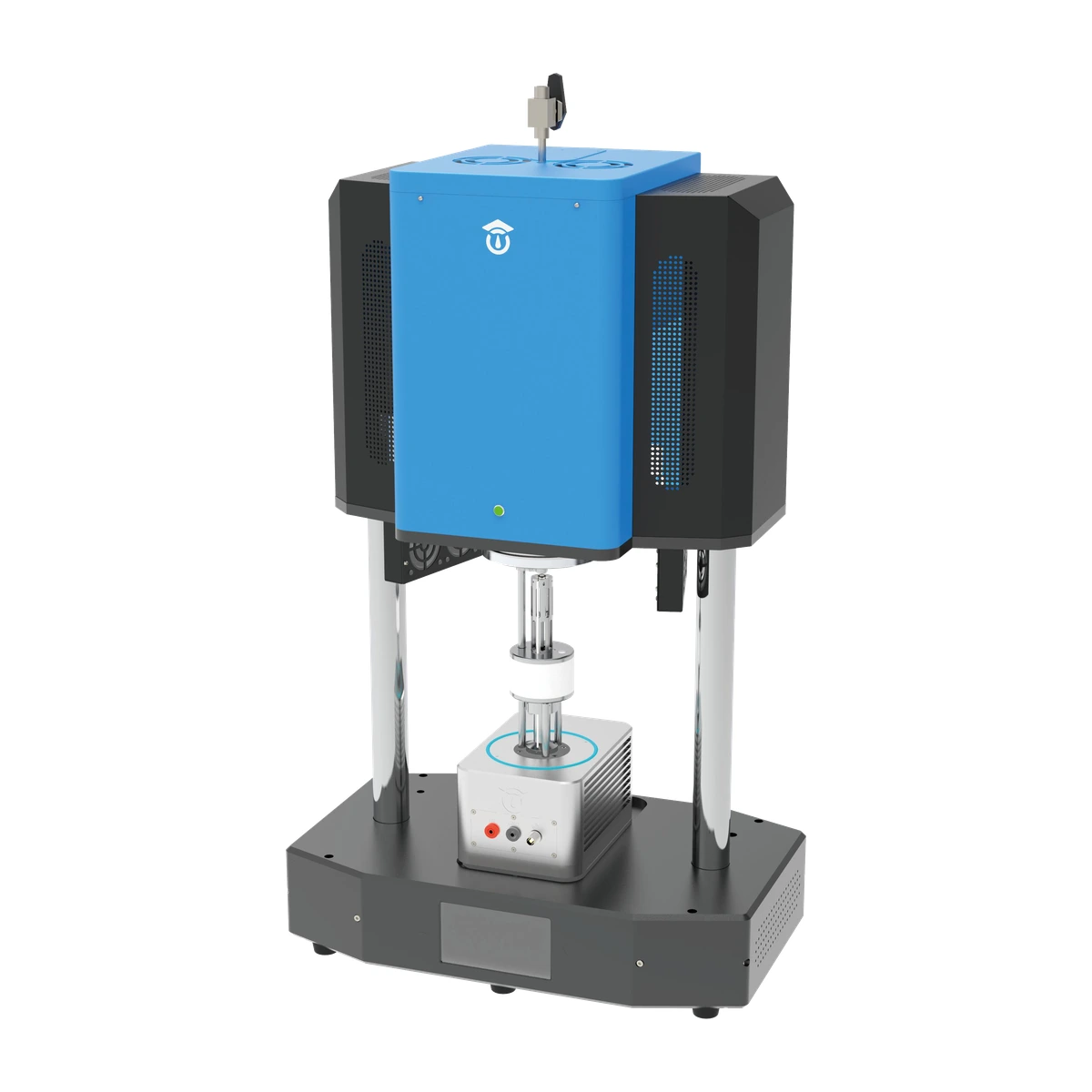
In the field of high-temperature clean energy technologies, additive manufacturing (3D printing) of functional porous ceramics has emerged as a transformative frontier. Research groups worldwide are engineering porous monolithic architectures—such as 3D-printed calcium carbonate and calcium oxide (CaCO₃/CaO) lattices for calcium-looping thermochemical energy storage, direct Joule-heated chemical reactors, and catalytic ceramic scaffolds.
While pristine CaCO₃ and CaO are electrical insulators (volume resistivity exceeding 10¹² Ω·cm), introducing conductive phases (such as carbon nanotubes, graphene networks, refractory metals, or conductive ceramic oxides) transforms these porous matrices into functional electro-thermal conductors. Once the conductive filler exceeds the percolation threshold, passing electrical current directly through the porous ceramic skeleton induces instantaneous, volumetric Joule heating (P = I²R), achieving operating temperatures up to 1000°C with thermal efficiencies unattainable by external radiative furnaces.
However, characterizing the fundamental electrical transport properties—resistance R(T), volume resistivity ρ(T), and electrical conductivity σ(T)—of these functional porous monoliths from ambient temperature up to 1000°C presents severe experimental roadblocks. Researchers routinely report crushed porous struts, open-circuit artifacts mid-run, and unrepeatable data.
Below is an engineering analysis of the five central experimental challenges encountered when testing fragile, porous 3D-printed ceramic monoliths, and the specific fixture mechanics developed to resolve them on the MatMeas RTS-1000C High-Temperature Conductive Material Resistivity System (upgraded generation of the legacy RMS-1000C platform).
Challenge 1: The Contact Force Dilemma — Preventing Micro-Crushing of Fragile Porous Skeletons
[Conventional Fixture] ──► Rigid Screws / Heavy Springs (> 5-15 N) ──► Crushed Porous Struts & Local Spalling
                                           VS
[MatMeas Architecture] ──► Calibrated Elastic Preload (0.2-0.8 N) ──► Zero Structural Damage & Stable Contact
The Engineering Problem:
Porous 3D-printed ceramic monoliths are characterized by high open porosity (typically 40% to 75%) and delicate sintered strut walls often measuring only 100 to 400 μm across. When specimens are shaped into small rectangular test bars—such as 5 × 5 × 10 mm or 5 × 5 × 20 mm—their compressive crushing strength is markedly lower than that of dense bulk ceramics.
Conventional high-temperature test fixtures utilize rigid screw clamps or heavy spring-loaded pins designed for dense metals or solid graphite blocks. These standard fixtures typically exert localized contact forces between 5 N and 20 N. On a delicate porous ceramic bar, this force concentrates on microscopic asperities and thin cell walls, causing immediate micro-cracking, strut collapse, and localized pulverization during clamping.
The Engineering Solution:
To achieve non-destructive electrical contact without pre-deposited metallized coatings, the system deploys a calibrated micro-force elastic contact mechanism:
- Contact force is strictly regulated within the window of 0.2 N to 0.8 N.
- This force is sufficiently compliant to eliminate strut fracture and cell wall collapse, yet provides adequate mechanical engagement to penetrate surface oxide films and establish stable ohmic contact against the conductive ceramic phase.
Challenge 2: Thermal Creep & Spring Relaxation — Moving Elastic Elements to the Cold Zone
[HOT ZONE: Up to 1000°C]
  ┌────────────────────────────────────────────────────────────────────────┐
  │  Dense 99% Zirconia (ZrO₂) Guiding Pillars                             │
  │  Pure Platinum (Pt) Current Interfaces & Tungsten Carbide (WC) Probes  │
  │  [Porous 3D-Printed Specimen: 5 × 5 × 20 mm]                           │
  └───────────────────────────────────┬────────────────────────────────────┘
                                      │ Dense Zirconia Force Pushrods
                                      ▼
[COLD ZONE: Base at Room Temperature < 50°C]
  ┌────────────────────────────────────────────────────────────────────────┐
  │  Calibrated Linear Spring Mechanism                                    │
  │  • Completely isolated from the thermal hot zone                       │
  │  • Zero thermal annealing / zero creep relaxation up to 1000°C         │
  │  • Constant 0.2 N - 0.8 N force maintained across heating & cooling    │
  └────────────────────────────────────────────────────────────────────────┘
The Engineering Problem:
Many commercial high-temperature probe stations claim operation up to 800°C or 1000°C, yet suffer from data loss during heating ramps. The physical root cause is thermal stress relaxation (annealing) of metallic springs.
When a spring mechanism is housed inside or immediately adjacent to the furnace hot zone, exposure to temperatures above 500°C rapidly relieves mechanical temper in alloy springs (including Inconel). The spring loses its elastic modulus and relaxes, causing contact force to decay to near zero. As a result, the probe loses physical contact with the sample, producing catastrophic resistance spikes or total open circuits during thermal plateaus and cooling cycles.
The Engineering Solution:
The RTS-1000C platform resolves this by implementing Cold-Zone Spring Isolation:
- The calibrated elastic spring mechanism is mechanically decoupled from the furnace hot zone and located in the lower ambient-temperature test stand base (< 50°C).
- Mechanical preload is transmitted vertically into the furnace chamber through high-purity, rigid 99% Zirconia (ZrO₂) pushrods.
- Because the spring never experiences elevated temperatures, it exhibits zero thermal creep and zero loss of temper. The specimen experiences perfectly constant contact pressure from room temperature through the 1000°C peak and back to ambient.
Challenge 3: Small-Specimen Metrology & Streamline Fringing (5×5×10 to 5×5×20 mm)
                  ┌──────────────────────────────┐
                  │ Regulated DC Current Source  │
                  └──────────────┬───────────────┘
                                 │ I (+ / - Delta Mode)
            ┌────────────────────┴────────────────────┐
            ▼                                         ▼
      [Current Lead 1]                          [Current Lead 2]
      (Outer Platinum)                          (Outer Platinum)
         │                                             │
      ┌──▼─────────────────────────────────────────────▼──┐
      │          POROUS 3D-PRINTED CERAMIC MONOLITH       │
      │  ◄────── d_in ─────► ◄──── L ────► ◄───── d_in ──►│
      └──▲───────────────────────▲─────────────────────▲──┘
         │                       │                     │
         └──────────┐ ┌──────────┘                     │
                    │ │                                │
             [Voltage Sensing]                         │
             (Tungsten Carbide)                        │
                    │ │                                │
            ┌───────▼─▼──────────────────────┐         │
            │ Ultra-High Impedance Voltmeter │         │
            │ (> 10 GΩ Input Resistance)     │         │
            └────────────────────────────────┘         │
The Engineering Problem:
Fabricating large 3D-printed ceramic specimens is often cost-prohibitive or prone to shrinkage cracking during debinding and sintering. Consequently, researchers typically produce small rectangular bars measuring approximately 5 × 5 × 10 mm up to 5 × 5 × 20 mm.
Applying a standard two-wire technique to such small bars fails completely because contact resistance (R_contact) and lead resistance (R_lead) can exceed the true bulk resistance (R_bulk) by several orders of magnitude:
R_measured = R_bulk(T) + 2·R_contact(T) + 2·R_lead(T)
Furthermore, if the potential sensing probes are positioned too close to the current injection terminals, non-uniform current streamlines (current crowding) introduce severe geometrical distortion into the resistivity calculation.
The Engineering Solution:
The RTS-1000C integrates a dedicated Four-Wire Kelvin Monolith Fixture:
- Parallel Streamline Geometry: Current is injected through planar Platinum outer contacts, while high-impedance voltage sensing taps are positioned along the central gauge length L. The buffer distance d_in between outer current terminals and inner voltage taps satisfies the geometric criteria d_in ≥ 1.5·√(w·t), ensuring that current streamlines are fully parallel within the voltage sensing zone:
ρ(T) = (ΔV(T) / I) × (w · t / L) = R(T) × (A / L)
σ(T) = 1 / ρ(T)
Where:
- w: Specimen width (meters)
- t: Specimen thickness (meters)
- A = w · t: Specimen cross-sectional area (square meters)
- L: Calibrated distance between voltage sensing probes (meters)
- R(T): Measured bulk four-terminal resistance (ohms)
- Dimensional Alignment Slots: Precision-machined Zirconia alignment channels securely hold 5 × 5 × 20 mm (and 5 × 5 × 10 mm) bars. This guarantees fixed, repeatable probe spacing L and prevents lateral rotation during motorized furnace movement.
- Automated Bipolar Current Reversal: High temperatures inevitably generate Seebeck thermoelectric offset voltages (V_Seebeck) across dissimilar ceramic-metal probe junctions. The RTS-1000C deploys high-speed bipolar delta-mode current reversal (+I, -I), mathematically canceling V_Seebeck in real time:
Forward Step: V_1 = (+I)·R_x + V_Seebeck
Reverse Step: V_2 = (-I)·R_x + V_Seebeck
Isolated Resistance: R_x = (V_1 - V_2) / (2·I)
Challenge 4: Protecting Conductive Additives from Thermal Oxidation at 1000°C
The Engineering Problem:
In CaCO₃/CaO-based conductive ceramics, electrical conductivity is imparted by nanocarbon networks (CNTs, graphene, carbon black) or reactive metallic micro-particles. In ambient air, carbonaceous additives undergo rapid, irreversible oxidation above 400°C:
C_additive + O₂ ──► CO₂ ↑ (rapid thermal burn-off above 400°C)
If residual oxygen exists in the test furnace, the conductive pathways oxidize into gas within minutes. The specimen's measured resistance will jump by six to eight orders of magnitude, reflecting additive destruction rather than intrinsic material behavior.
The Engineering Solution:
The RTS-1000C is engineered with an integrated hermetic quartz hot zone supporting a strict controlled atmosphere protocol:
| Protocol Stage | Operational Target | Engineering Mechanism & Purpose |
|---|---|---|
| Stage 1: Pre-Evacuation | Base vacuum < 1.0 × 10⁻¹ Pa | Evacuates atmospheric oxygen and desorbs trapped moisture from porous cellular micro-cavities. |
| Stage 2: Inert Gas Backfill | High-Purity Nitrogen (N₂ ≥ 99.999%) or Argon | Establishes a chemically inert protective blanket prior to initiating thermal ramp. |
| Stage 3: Dynamic Purge Flow | Continuous laminar flow (50–100 sccm) | Positive-pressure purge prevents back-diffusion of ambient air through fittings during high-temperature plateaus. |
| Stage 4: Thermal Ramp Rate | 2°C/min to 5°C/min (PID) | Regulated heating avoids thermal shock fracture in low-expansion porous skeletons. |
Challenge 5: Dynamic Resistance Span & Physical Verification on Brittle Monoliths
1. Broad Dynamic Span: 10 nΩ to 100 MΩ
Functional composites undergo massive impedance transitions. At room temperature, a heavily doped composite may exhibit a resistance of a few milliohms. As temperature rises to 1000°C, phase transitions, contact sintering, or intrinsic semiconducting excitation can shift resistivity by multiple orders of magnitude.
The RTS-1000C provides a continuous dynamic measurement envelope from 10 nΩ to 100 MΩ, tracking orders-of-magnitude transitions without manual amplifier switching.
2. Dual Measurement Modes
The system software supports two complementary operational regimes:
- Stabilized Temperature Mode (Primary): The furnace steps through user-defined thermal setpoints (e.g., every 50°C or 100°C), dwelling until thermal equilibrium is established before logging steady-state R, ρ, and σ.
- Continuous Dynamic Sweep (Complementary): Continuous real-time logging during ramp-up and cool-down at rates of 1–5°C/min, allowing researchers to observe kinetic phenomena, phase transitions, and thermal hysteresis.
3. Empirical Hardware Verification on Brittle Semiconductor Bars
The mechanical viability of this fixture is verified through extensive testing on brittle semiconductor Silicon Carbide (SiC) rectangular bars and refractory metallic conductors:
[Physical Validation Record]
1. Metallic Alloy Monoliths    ──► Linear ρ(T) increase up to 1000°C; zero baseline drift
2. Semiconductor SiC Monoliths ──► Verified in dedicated 4-wire bar fixture; stable ohmic contact up to 1000°C
3. Low-Resistance Bulk Alloys  ──► Sub-micro-ohm resolution with automated bipolar thermal EMF cancellation
Testing on brittle Silicon Carbide bars confirms that fragile rectangular specimens can be securely held, electrically energized, and thermally cycled up to 1000°C without mechanical failure or probe dislocation.
Laboratory Pre-Test Checklist: Ensuring Valid Results
Before initiating full-scale high-temperature characterization on 3D-printed porous monoliths, research teams should verify two preliminary criteria:
- Room-Temperature Percolation Check:
Ensure that the concentration of conductive additives exceeds the percolation threshold. A rapid ambient two- or four-wire continuity check should register a measurable baseline within the system's 10 nΩ to 100 MΩ range. If the sample registers open-circuit (> 10⁸ Ω) at room temperature, it behaves as an electrical insulator and should instead be characterized using high-resistance electrometer methods (e.g., MatMeas HTS-1000HR) or broadband dielectric spectroscopy (MatMeas DMS-1000). - Contact Face Parallelism:
Inspect the 3D-printed surface strata. While the elastic fixture accommodates modest surface roughness, ensuring that opposite contact faces are substantially parallel prevents localized stress risers and promotes uniform current injection across the cross-section.
Dual Engagement Pathways: Capital Instrumentation & Testing Services
To support university departments, national energy institutes, and industrial R&D teams characterizing advanced functional ceramics, MatMeas offers two engagement models:
- Turnkey Capital Instrument Procurement:
For research laboratories establishing permanent high-temperature electrical transport testing capabilities, explore complete specifications, vacuum chamber options, and dedicated monolith fixtures on the MatMeas RTS-1000C Product Page →. - Authorized Contract Sample Testing Services:
For research groups conducting preliminary exploratory studies, unbudgeted feasibility trials, or pre-procurement evaluations, submit your 3D-printed ceramic monoliths to our certified characterization laboratory. Our engineers deliver full-temperature R(T), ρ(T), and σ(T) datasets under controlled atmospheres via the MatMeas Testing Services Portal →.
Request High-Precision Testing Solutions
Get expert guidance and customized instruments for your functional materials project.