Piezoelectric d33 Constant Testing and Procedures
Technical News
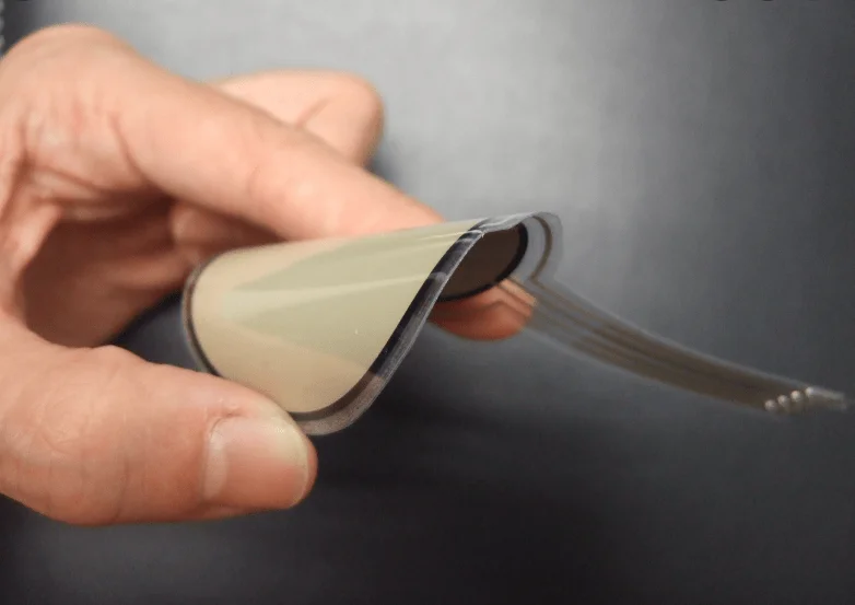
The longitudinal piezoelectric charge coefficient, designated d33, is universally recognized as the primary figure of merit for functional piezoelectric ceramics, single crystals, and composite transducers. Quantifying the induced electrical charge per unit of applied mechanical force (expressed in picocoulombs per newton, pC/N) or, conversely, the mechanical strain generated per unit of applied electric field (in meters per volt, m/V), d33 directly governs the sensitivity of ultrasonic hydrophones, precision positioning actuators, and energy harvesters.
Despite the conceptual simplicity of quasi-static Berlincourt d33 testing, industrial production lines and academic laboratories routinely report severe measurement discrepancies exceeding 15% to 30% for identical ceramic lots. These discrepancies arise from systematic experimental errors: improper static pre-stress clamping forces that mechanically clamp domain wall motion, non-parallel electrode geometry causing shear strain cross-talk, failure to account for post-poling domain relaxation aging, and insufficient calibration traceability. Establishing reproducible, high-accuracy d33 characterization requires strict adherence to standardized measurement SOPs.
Constitutive Electromechanical Equations and the Berlincourt Charge Integration Principle
The direct and converse piezoelectric effects in anisotropic crystalline media are defined by linear piezoelectric constitutive equations according to IEEE Std 176:
D3 = d33 · T3 + ε33T · E3 (Direct Effect)
S3 = s33E · T3 + d33 · E3 (Converse Effect)
where D3 represents the dielectric displacement along the polarization axis, T3 is the applied mechanical stress, S3 is the resulting longitudinal strain, E3 is the applied electric field, s33E is the elastic compliance at zero electric field, and ε33T is the dielectric permittivity under zero stress. Under zero electric field boundary conditions (E3 = 0), the longitudinal charge coefficient is formally defined as:
d33 = (∂D3 / ∂T3)E=0 = Qgenerated / Fapplied
The quasi-static Berlincourt method operates by subjecting the ceramic coupon to a composite force consisting of a constant static clamping pre-load (Fstatic) superimposed with a small low-frequency sinusoidal dynamic force (Fdyn · sin ωt):
Ftotal(t) = Fstatic + Fdyn · sin ωt
The low-frequency dynamic mechanical excitation (typically calibrated at 110 Hz to prevent electromagnetic grid hum at 50/60 Hz and stay well below structural acoustic resonance) generates an alternating piezoelectric charge Q(t). The measurement circuit integrates this charge across a calibrated internal reference capacitor Cref, producing an output AC voltage VDUT:
VDUT = QDUT / Cref = (d33,DUT · Fdyn) / Cref
A built-in reference standard consisting of a highly stable quartz crystal or pre-calibrated hard PZT element subjected to the identical mechanical force Fdyn generates a reference voltage Vstd:
Vstd = (d33,std · Fdyn) / Cref
Taking the direct ratio of the two integrated voltage amplitudes eliminates the absolute magnitude of the dynamic force Fdyn from the equation, yielding a direct relative extraction:
d33,DUT = d33,std · (VDUT / Vstd)
Comparison of Piezoelectric d33 Metrology Techniques
Depending on specimen geometry, mechanical stiffness, and operating frequency, materials engineers employ different characterization methods to measure longitudinal electromechanical response.
The matrix below compares the three primary international techniques for d33 evaluation:
| Metrology Technique | Physical Operating Principle | Excitation Frequency Range | Static Clamping Load Impact | Specimen Form Factor | Measurement Uncertainty |
|---|---|---|---|---|---|
| Quasi-Static Berlincourt Method | Direct piezoelectric effect via low-frequency dynamic force | 50 Hz to 250 Hz (typically 110 Hz) | Critical: Must balance electrical contact without domain pinning (~0.5–2 N) | Bulk discs, thick plates, ceramic rings (>0.5 mm thick) | ±1.0% to ±2.0% |
| Dynamic Mechanical / Force Analysis | Wide-frequency cyclic loading with lock-in amplification | 0.1 Hz to 1 kHz | High capability: Adjustable preload up to 100 N for pre-stress studies | Bulk components, actuators, multi-layer stacks | ±1.5% to ±3.0% |
| IEEE Resonance / Impedance Method | Electrical resonance extraction of kt and k33 via impedance analyzer | Acoustic resonance (100 kHz to 10 MHz) | Zero mechanical contact (free suspension in test fixture) | Thin slender rods (L » W, T) or thin discs | ±2.0% to ±5.0% |
Standardized Step-by-Step Testing SOP and Calibration Verification
To achieve reproducible d33 measurements compliant with IEEE Std 176 and IEC 60483, testing personnel must execute the following five-stage standard operating procedure:
-
Mandatory Post-Poling Aging Stabilization: Following high-voltage polarization, ferroelectric domains contain high residual internal stresses. Domain relaxation causes d33 to decay logarithmically over time:
d33(t) = d33(t0) · [1 − kaging · log₁₀(t / t0)]
where kaging is the aging rate per decade of time (typically 1% to 2% for soft PZT). Testing immediately after poling yields artificially elevated values. A stabilization dwell of at least 24 hours (and ideally 10 days for precision calibration standards) at 25°C is mandatory before formal measurement.
-
Reference Calibration Verification: Prior to mounting the unknown device under test (DUT), insert a certified reference standard (e.g., standard quartz cylinder or calibrated PZT disc with NIST or PTB traceability). Verify that the instrument reads within ±1 pC/N of the certified value.
-
Specimen Placement and Axial Alignment: Place the test disc centered between the upper and lower hemispherical contact probes. The geometric center of the electrode must align with the probe axis. Eccentric contact introduces bending moments that superimpose spurious transverse d31 charges onto the longitudinal d33 reading.
-
Static Preload Calibration: Engage the mechanical clamping screw until the spring-loaded indicator reaches the calibrated force window (typically 0.5 N to 1.5 N). Excessive pre-stress (>5 N) suppresses ferroelastic 90° domain wall mobility, causing an artificial underestimation of d33 by 5% to 15%.
-
Polarity and Phase Verification: Observe the sign displayed on the meter. Compression along the positive polarization direction generates positive charge on the positive electrode face. Reversing the sample orientation in the fixture must invert the sign while preserving the absolute magnitude within ±1%.
The table below summarizes the temporal stabilization of d33 during post-poling aging:
| Elapsed Time Post-Poling | Normalized Residual Internal Stress | d33 Stability Level | Recommended Operational Action |
|---|---|---|---|
| 0 to 2 Hours | High (>85% residual stress) | Highly unstable (+8% to +12% drift) | In-process monitoring only; do not ship or calibrate |
| 24 Hours | Moderate (~35% residual stress) | Initial stabilization (within ±3% of baseline) | Standard quality control screening for production lots |
| 7 Days | Low (<15% residual stress) | High stabilization (within ±1% drift) | Precision device assembly and transducer matching |
| 10 to 30 Days | Fully relaxed (<5% residual stress) | Thermally consolidated (asymptotic baseline) | Metrology calibration standards and benchmark verification |
Hardware Error Elimination with the MatMeas PCA-1000 System
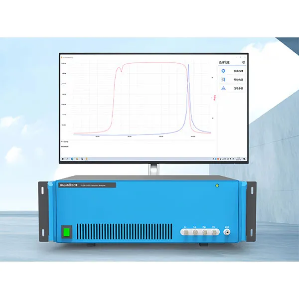
To eliminate operator dependency and clamp-force variability, the MatMeas PCA-1000 Piezoelectric Parameter Analyzer integrates precision electromagnetic dynamic force generation with automated pneumatic pre-stress regulation.
The PCA-1000 utilizes hemispherical beryllium-copper or gold-plated contact probes that accommodate slight non-parallelisms in ceramic coupons without edge chipping. Driven by a dedicated digital signal processor (DSP) operating at 110 Hz, the system measures longitudinal d33 across an expansive span from 1 pC/N up to 4,000 pC/N with 0.1 pC/N resolution and ±1% accuracy. High-precision capacitive load cells continuously monitor static pre-stress, locking the clamping force to user-specified thresholds (e.g., exactly 1.0 N ± 0.05 N). The instrument supports automated batch logging, polarity phase discrimination, and direct calculation of electromechanical coupling factors kp when coupled with resonance impedance analysis.
Frequently Asked Questions
Why does increasing the static clamping force cause a measured d33 value to decrease?
Piezoelectric response in ferroelectric ceramics consists of intrinsic lattice distortion (single-crystal response) and extrinsic ferroelastic domain wall motion (movement of 90° domain walls in tetragonal ceramics). Extrinsic domain wall contributions account for up to 50% to 70% of room-temperature d33 in soft PZT formulations. Applying excessive static mechanical pre-stress clamps the domain walls within the crystal lattice, severely restricting their ability to vibrate under the small AC dynamic test force. This mechanical clamping artificially suppresses the extrinsic contribution, reducing the measured d33 by 10% or more.
What is the optimal frequency for Berlincourt d33 testing, and why is 110 Hz standard?
Quasi-static d33 meters universally operate between 100 Hz and 200 Hz, with 110 Hz established as the international benchmark. This frequency is deliberately selected to avoid 50 Hz and 60 Hz electrical mains power frequencies and their harmonics (100 Hz, 120 Hz), which easily induce electromagnetic pickup in high-gain charge amplifiers. Furthermore, 110 Hz is sufficiently low to remain far below any mechanical acoustic resonance of the ceramic sample, ensuring that the test satisfies quasi-static mechanical equilibrium.
Why must piezoelectric ceramics age for at least 24 hours after polarization before d33 testing?
Immediately after removal from high-voltage poling fields, ferroelectric ceramics contain severe internal anisotropic stresses resulting from forced 90° domain rotation against grain boundaries. Over the first several hours, loosely pinned non-180° domains undergo thermal and mechanical relaxation, and space-charge carriers redistribute to screen internal fields. This relaxation causes a predictable logarithmic decay in d33. Testing before 24 hours measures an unrelaxed transient state; waiting at least 24 to 48 hours allows the material to reach structural equilibrium.
Request High-Precision Testing Solutions
Get expert guidance and customized instruments for your functional materials project.